Part 1 of 2. This part deals with the rendering trends in the VFX industry today. Part 2 includes a run down of 14 of the most popular renderers for VFX. Many of the issues in this special two part series will also be covered in more depth in the July term at fxphd.com.
Introduction: which renderer?
Each Tuesday at ILM in the Presidio in San Francisco at the former military base on the northern tip of the San Francisco Peninsula overlooking the Golden Gate Bridge there is a lunch for all the ILM visual effects supervisors. It is a private lunch where they get to discuss anything and everything. ILM has an incredible wealth of visual effects supervisors with an astonishing collection of both Oscars and technical landmark innovations. “It is great. It is one of the great things about the company,” says supervisor Ben Snow.
Rendering often comes up in conversations. While that may not be a topic most directors focus on, it is these people and their respective leads on projects who must decide how they will achieve the incredible shots they bid, often with unparalleled realism on ever tighter budgets. ILM has a full site license of RenderMan and for many years primarily used it as their renderer, especially on creature work. But, as Snow explains, “we have had a lot of discussion at the supervisor level that we want to be renderer agnostic. If someone wants to use Arnold they should be able to. If I want to use RenderMan I should be able to.”
Pacific Rim. This shot rendered in Arnold at ILM.
ILM is not alone in seeing rendering as something in need of constant evaluation and far from a simple solution. Right now, ILM alone uses a range of renders from Arnold to RenderMan to V-Ray to newer tools like Modo.
As Snow described to fxguide, he had told the team at Pixar earlier that day, “I am old school ILM – and we were RenderMan people – almost RenderMan chauvinist actually. So I have always been a little bit biased towards them. On Pearl Harbor where we thought GI was the answer we worked hard to try and get it to work in Mental Ray and on Iron Man we looked at Mental Ray, to see if we could match the suits when shared with another vendor.” In the end they used RenderMan.
Star Trek: Into Darkness. This image rendered in Arnold at ILM.
“All renderers have strengths and weaknesses and different departments here at ILM use different renderers,” adds Snow. “Arnold became the next big thing and we were looking at that on the last few shows. But I have to say on the last few films we have really been jumping around on renderers. And in each case we have been porting the shader set between the renderers.” For example, Arnold was used on Star Trek: Into Darkness, Pacific Rim and The Lone Ranger this year at ILM, along with other renderers.
While RenderMan is the ‘gold standard’ by which other production renderers are judged, Arnold has certainly got the reputation as perhaps the fastest production renderer for many styles of projects – a point made to fxguide by not one but several of their competitors.
People can be very religious about their renderers!
Mark Elendt
Mantra, Side Effects Software
But beyond these two big players, there is an amazing number of production renderers and people are very passionate about which they prefer. And many of these other renderers are exceptionally good. V-Ray has been even more widely embraced than Arnold for its quality speed and more open community approach. Most people agree that Maxwell can often be used as a ground truth because of its dedicated light simulator approach and incredible accuracy. Once upon a time the renderers that shipped with applications were only used by those who could do no better, but Mantra and Modo’s renderer, for example, have gained real acceptance in their own right. And there are a host of newer renderers, some challenging GPU v CPU, others completely cloud based and no longer even rendering previews from the desktop.
An advanced Maxwell Render showing caustics.
In this article – a follow-up to fxguide’s extraordinarily popular Art of Rendering piece – we explore the state of play with renderers in the visual effects and animation fields. Part 1 provides background on the issues of the day, while Part 2 highlights each major renderer in some detail based on interviews done exclusively with each company. We also take a brief look at the future and question if the whole approach is not flawed?
1. Issues of the day
“Each pixel is just a single color but to come up with that color you have to look at the entirety of the environment.”
Rob Cook
Pixar RenderMan co-founder
In this first section we highlight the primary issues in the area of rendering. This year, RenderMan celebrates 25 years and (fxguide has a special feature on the history of RenderMan coming up). Rob Cook, co-architect and author of Pixar’s RenderMan, described rendering to fxguide as “each pixel (on the screen) is just a single color but to come up with that color you have to look at the entirety of the environment inside that pixel.”
Cook published in 1984 a key ray tracing paper that set up the idea of randomly sampling to reduce aliasing and artifacts. The paper is one of the landmark advances in ray tracing, and when the RenderMan spec was first published it accommodated ray tracing as a possible render solution. This is remarkable given that for many years Pixar’s own PRman implementation would not use ray tracing as it was considered far too computationally expensive and yet today – nearly 29 years after Cook’s paper – Pixar’s Monsters University was fully ray traced and using at its core the principles of that paper.
The rendering equation was presented by James Kajiya in 1986. Path tracing was introduced as an algorithm to find a numerical solution or approximation to the integral of the rendering equation. A decade later, Lafortune suggested many refinements, including bidirectional path tracing. Metropolis light transport, a method of perturbing previously found paths in order to increase performance for difficult scenes, was introduced in 1997 by Eric Veach and Leonidas J. Guibas.
The original rendering equation of Kajiya adheres to three particular principles of optics:
the principle of global illumination,
the principle of equivalence (reflected light is equivalent to emitted light), and
the principle of direction (reflected light and scattered light have a direction).
From informally surveying the industry, fxguide has identified some of the key trends in the following areas:
While there is a great amount of work being done in non-realistic rendering, especially in Japan, the overwhelming trend is to more realistic rendering. This means rendering with global illumination and providing images with bounce light, color bleeding, real world light samples, and – increasingly – the use of physically plausible shaders and lights.
The most widely used methods for GI are distribution ray tracing, path tracing, and point-based global illumination. Each of these has their advantages and limitations, both from a technical point of view and from the complexity they force upon the lighting artist or TD setting up the shot.
Monsters University: rendered in RenderMan by Pixar.
The first use of global illumination as noted in a recent paper (Multiresolution Radiosity Caching for Efficient Preview and Final Quality Global Illumination in Movies 2012 Per H. Christensen et al.) in a feature-length movie was for the movie Shrek 2. Here, PDI/DreamWorks computed direct illumination and stored it as 2D texture maps on the surfaces, and then used distribution ray tracing to compute single-bounce global illumination.
As the paper points out the use of 2D textures requires the various surfaces in the scene to be parameterized. “The irradiance atlas method is similar, but uses 3D texture maps (“brick maps”) so the surfaces do not need a 2D parameterization. Both methods use two passes: one pass to compute the direct illumination and store it (as 2D or 3D texture maps), and one pass for final rendering.” Irradiance maps are baked and not generated per frame as Sam Assadian from Clarisse iFX points out. “Irradiance maps flicker with low frequency noise – the worse kind.” By rendering once and storing the value, rendering is faster overall and consistent over time (temporally stable).
Path tracing is a form of ray tracing and it is a brute-force unbiased global illumination method that was first seen via the Arnold render in Monster House from Sony Pictures Animation. The advantages of path tracing are that it does not use complex shaders nearly as much as a biased or point cloud approach. Given the way a path tracer renders it can provide fast feedback during interactive lighting design. The problem with all ray tracers is noise. At the basic level to halve the noise you need to quadruple the number of rays. The promise, mathematically, of unbiased ray tracing is that given enough rays it will converge to a correct solution. Ray tracing is built on probability and if you fire enough rays, instead of sampling and estimating the result, the variance is reduced to 0, and the solution converges to the correct result. Of course, firing an infinite or extremely large number of complex rays is not viable especially with the nonlinear noise curve, so one has only three options:
• use a different clever solution – like brick maps and say a scan line renderer or a partial ray tracing solution
• write really fast and clever code that renders very quickly i.e. fast clever rays
• aim the majority of your rays where they matter the most i.e. aim those fast clever rays better
At the core of the ray tracing scheme is the notion of solving a lighting problem using samples, normally random samples decided by a probability distribution function, but to get GI, you also need to think about what other rays are fired off due to the material (the shader/BRDF etc) and how you sample the lights, or rather things that will contribute light. From on set we all know you can light with a bounce card, so to catch every object in a scene bounce light, and the biggest example of this is lighting with a giant light dome or what is known as image based lighting. In image based lighting a dome or sphere is mapped with an image, normally a HDR image. The whole dome or sphere contributes light to everything inside it, which is again why sampling this giant massive spherical light sensibly is important. After all we are trying to do nothing less than recreate the world in all its lighting complexity and how every part of it affects every other part of it.
Like any sphere it is easy to think that there is energy bouncing around in the form of light, which should all add up. In other words if a light bounces off a table the bounce light would never be more than the light coming from the light source, and if one moves the light further away, then the bounce would not only seem less strong, it would actually reduce according to the inverse square law. We all know this from moving any light in the real world. This idea of correct light behavior and correct material behavior is what is being referred to in “physically plausible lighting and shaders”. (For this article we will use the more relaxed term physical lighting and physical shaders, but they are of course nearly always just a very close approximation).
Do you have to use ray tracing and physical lights and shaders? Absolutely not.
Millions of frames of animation and effects have been produced without either, but the trend is towards both, not for everything, but in the world of VFX and animation it is the dominant trend. We will try and highlight non-ray tracing solutions, and there are many, but the state of the art today is centered around a “rays race” to produce better results, that are easier to light and yet do not explode memory and render budgets.
GI Joe: Retaliation. This image rendered in V-Ray at ILM.
One of the biggest disadvantages of ray tracing is its memory requirements. One of the remarkable historical aspects is that RenderMan, so as to beat the RAM budget of 25 years ago and allow anything to be rendered of any complexity, still today contains both a REYES scan line renderer and a ray hider. RenderMan is remarkable in not only its successful history but the sheer success of its foundering scientist vision to be able to define a spec – an approach that could still be valid today, and would be as forward looking at it was. We will cover some of that history below but today RenderMan stands alongside Arnold, V-Ray, Maxwell, and newer programs like the cloud based Lagoa and the GPU Octance renderers as a program that is trying to render faster and more accurate ray traced images to an ever competitive environment.
Maxwell Render with SSS.
How competitive? Since we wrote the first Art of Rendering story, just 18 months ago, the landscape has changed dramatically. New renderers and whole new approaches have been released. There have been dramatic improvements, renderers have died, others have been bought, and there is no sense that the process is anywhere near over. Rendering, once a fairly predictable evolutionary space, has become like a quickly moving landscape. For this story alone we have done over 20 interviews and we will be covering 14 major production rendering platforms. We have aimed to focus on production renderers for animation and VFX and not even really touch on game engine rendering, GPU rendering and mobile offerings. Art of Rendering saw many compliments but also a host of complaints. To paraphrase a quote from the first article, “rendering is now a bit like a religion.”
1.2 Ray tracing vs point solutions
Ray tracing is only one approach to GI and its main rival is point-based global illumination. Actually the terms are confusing as strictly speaking one can have a non-fully ray traced solution that still involves some firing of rays. But for now let’s consider ‘ray tracing’ to mean fully unbiased ray tracing or path tracing.
Before discussing ray tracing it is important to understand how point based GI works, as many solutions in the real world use a combination of results. For example, in Pixar’s latest feature Monsters University, the film moved to primarily ray tracing and physically based lighting and shading, but still for the sub surface scattering (SSS) it used a point based solution (although that will not be true of the next Pixar feature). SSS is the way light softens beneath the skin as especially the red light wavelengths scatter and produce the waxy look of skin vs the flat look of plastic. SSS is key to character animation and is not new – for example, Joe Letteri (senior VFX supervisor Weta Digital) used it extensively in the original Lord of the Rings films (see this 2004 fxg interview) and it was key to the original ground breaking look of Gollum. But SSS is very expensive and hard to achieve in a brute force ray tracer, but very achievable using a point source solution.
Weta Digital’s Joe Letteri talks to fxguide about the advent of physically based lighting and rendering at his studio.
Point-based GI is relatively new in its own right and it is fast. Plus, unlike ray tracing, it produces noise-free results. “It was first used on the movies Pirates of the Caribbean 2 and Surf’s Up, and has since been used for more than 40 other feature films” (2012 Per H. Christensen et al.)
Point-based GI is a multi-pass method:
In the first pass, a point cloud is generated from directly illuminated micropolygons
In the second pass, n−1 bounces of GI are computed for the point cloud. (The 2nd pass can be skipped if only a single bounce is needed)
In the third pass, the indirect illumination from the point cloud is computed and rendered
Due to its multi-pass nature, a point-based method is not suitable for interactive lighting design. The latest version of this approach from Pixar is outlined in the 2012 Per H Chistensen paper. It is based on storing post-shading radiosity values from grids of micropolygon vertices. By caching the radiosity, the Pixar team captured and reused both direct and indirect illumination and reduced the number of shader evaluations. By shading a grid of points together rather than shading individual points, their approach was suitable for a REYES-style SIMD shader execution (non-ray traced in other words). The authors noted that their method was similar to Greg Ward’s irradiance cache approach, Greg Ward being a true pioneer in many areas of radiosity and HDRs (see our fxg Art of HDR story from 2005).
At the time of beginning MU, Pixar had been planning on doing a non-full ray traced solution, the problem being that ray traced GI in production meant MU scenes with huge geometry and complex shaders. At Pixar the team saw the bottleneck not as the ‘raw’ ray tracing time, but the time spent evaluating:
the displacement,
light source, and
surface shaders at the ray hit points. Note: the shader evaluation time includes texture map lookups, procedural texture generation, shadow calculation, BRDF evaluation, shader set-up and execution overhead, calls to external plug-ins, etc.
The point solution meant “we reduce this time by separating out the view-independent shader component — radiosity — needed for global illumination and caching it. During distribution ray tracing global illumination these radiosities are computed on demand and reused many times. As a by-product of caching these shading results, the number of shadow rays is reduced.”
The radiosity cache is implemented in Pixar’s PhotoRealistic RenderMan renderer that supports both progressive ray tracing and REYES-style micropolygon rendering. The cache contains multiple resolutions of the radiosity on the surface patches in the scene.
“The resulting single-pass global illumination method is fast and flexible enough to be used in movie production, both for interactive material and lighting design and for final rendering. Radiosity
caching gives speed-ups of 3x to 12x for simple scenes and more than 30x for production scenes,” the 2012 paper quotes. Indeed, at last year’s 2012 RenderMan User Group, incredibly impressive comparisons were shown between early approaches and the new RenderMan approaches.
So why try and go to ray tracing? If other clever methods are able to produce orders of magnitude faster results – why even explore fully ray traced solutions and how can ray tracing be made to render as fast as possible? What is even more interesting is that even for Pixar’s own MU, the point solution was only used on SSS (with a method that used Jensen’s now famous dipole (or version of) solution which models SSS as diffusion – look at a given point is the integral over the surface of the product of a diffusion kernel and the irradiance (incident illumination) on the surface). Why did Pixar even go near fully ray traced on MU?
1.2.1. Physically Plausible Lighting and Shading
The overriding trend at the moment is to move to a physically based shading and lighting model. Marcos Fajardo of Solid Angle – the company behind Arnold – remarked that every (production) studio in the world has moved over to being able to work this way or is in the process of moving now. “That is happening right across the industry, ever single company you talk to is either in the middle of it or has already moved, and this is something I have been working towards for the last ten years or so, so I am really happy to see that happening – finally.” Fajardo should be credited as one of the greatest advocates and enablers of this massive shift in the industry. Solid Angle is very much at the forefront of the industry-wide move to path traced GI with physically plausible lighting and shading in a production environment (meaning in a cost effective way with ever tighter schedules).
Central to the popularity of path traced unbiased ray tracing is the desire to just make life similar for the lighting artists while making the pictures even more realistic.
In some old pipelines an artist could be handed a set up with a few hundred lights, plus extremely complex shaders – which are their own C ++ code-style clever box of tricks to pull off what was needed. Lighters would sometimes just have to sit and turn on and off lights to just work out what everything was doing.
Most companies would not claim that implementing physical lights and shaders made the rendering faster per say, but quite a few companies believe it makes the artist’s role much easier and frankly artist hours are more expensive than render hours by several orders of magnitude.
Image from Iron Man 2.
But the energy conservation and physical lights and shaders are not just the limit of path tracing new renderers. ILM adopted this approach some time ago with Iron Man 2. (See our lengthy interview with ILM’s Ben Snow from 2011).
From that story the process actually started in the film before Iron Man 2 – it started on Terminator: Salvation:
Terminator used a new more normalized lighting tool, not on every shot but on a couple of big hero sequences. The move to the new tool did spark somewhat of a holy war at ILM. Many of the team were happy with the tools and tricks that they had, and in fairness were using very effectively. So in the end the approach on Terminator was a hybrid and many of the cheat tools that artists knew and loved were enabled so that people could still use those tools on the film, and tweak lights in a way that was not physically correct.
The team at ILM implemented for Iron Man 2 a system of energy conservation:
The new system uses energy conservation which means that lights behave much more like real world lights. This means that the amount of light that reflects or bounces off a surface can never be more than the amount of light hitting the surface.
For example, in the traditional world of CG the notion of specular highlights and reflection were separate controls and concepts, as were diffuse and ambient light controls. So under the previous model if you had three lights pointing down (three beams one from each spot to a surface below), if the specsize is varied, the specular from the point light doesn’t get darker as the specsize increases. “Indeed this is the specular model we have been using for years at ILM actually gets much brighter with grazing angles so the actual specular values are very hard to predict,” says Snow.
Old lighting tool (ILM)Energy conservation tool (ILM)
Under the new energy conservation system, the normalized specular function behaves in the same way that a reflection does. As the specsize increases, the intensity of the specular goes down. Previously the system required the artist to know this and dial down the specular as the highlight got broader. While a good artist would know to do this, it had to be dialed in in look development, but different materials on the same model might behave differently, and of course objects would behave differently in different lighting environments and would have to be hand tweaked in each setup.
This ground breaking work started a fire that has spread throughout the industry. Now entire rendering systems are being set up that allow only for physically based lighting and shading.
But the system did something else, it accelerated the work ILM was doing with IBL. See below.
1.2.2. Importance sampling and multiple importance sampling (MIS)
If you do move to a system of ray tracing from above, one of the key things to be doing is as we stated “aiming those fast clever rays better.” But what does that mean?
Given that a large number of rays are going to be needed to solve some parts of the scene successfully, it is ideal to increase sampling where and when you need it while not wasting effort where you don’t. This is the art of importance sampling, (IS) as the name implies – sampling where it is important.
There are four levels of IS at the moment in the industry:
undirected brute force renderers which do not have IS
renderers that have it for just say environment lights or dome lights: environment sampling eg. Modo
renderers that have it for both lights and materials and intelligently balance the two: multiple importance sampling (MIS) – this could arguably be considered ‘state of the art’, eg RenderMan
advanced MIS – applying IS to a range of other solutions as well such as SSS eg. Arnold
The concept of MIS is not new. Eric Veach first discussed it in his Ph.D. dissertation, Stanford University, December 1997. This was followed by a key SIGGRAPH presentation the next year. So key is this work that Arnold founder Marcos Fajardo says he re-reads it every year or two, “…and ever since he published it, every single researcher has been reading that thesis – which is amazing by the way,” points out Fajardo. Veach’s understand of rendering is so deep and what is all the more remarkable is its 1997 publication date (as an aside, Veach went on to Google to develop algorithms for Adsense and made millions of dollars according to Fajardo who could not be more happy to see Veach rewarded).
Key implementations of this ground breaking MIS work in the current renderers environment has been done by Christophe Hery while at ILM with Simon Premoze (who was a research engineer at ILM, then at Dneg until recently). Premoze has since done courses at SIGGRAPH and MIS has become a critical part of rendering with ray tracing.
Christophe Hery implemented the MIS used on MU and it worked off a Power 2 formula also from Veach’s original Ph.D. Interestingly, this is one of the few occasions in recent times where the software used by Pixar was slightly out of step with the public RenderMan. Far from this being a deliberate withholding, it seems Pixar almost over ran the RenderMan team’s schedule of implementation, but this is now getting back in sync, such was the dramatic nature of the adjustment to the new approach. (You can learn more about the physically plausible shaders in MU in our 2013 fxguide article here).
To understand the power of MIS one need only refer to the original Veach doctorate – which is still as relevant today.
Below is a picture from that paper showing on the left the IS favoring the materials of BRDF samples, on the right it favors the lights in terms of sampling. There are 5 lights in both shots which are the same set-up apart from the IS settings. The fire lights are 4 lights at the back of shot and one overhead to just see what is in our space. If we ignore the top light – the back 4 lights are all of equal energy – so as the size of the light gets bigger – it appears to dull from bright white. In front are 4 panels angled to reflect the lights behind. The back panel is glossy, the front panel is much more diffuse.
Notice how when favoring the BSDF the tiny point light on the left is poorly sampled and thus on the rough bottom plane on the bottom left it is very noisy, but in the same BSDF the light on the right is reflected well – as it is big and easily reflected from the higher sampling on the material. By contrast, if we favor the light sampling, then the rough surface produces a nice spread out light effect from the hot tiny light, but the big light on the right is very noisy. Clearly we want to sometimes favor the BRDF (BSDF) and sometimes the lights – it depends on how diffuse the surface is and how big the lights are.
Thankfully this is exactly what MIS does. So much so it is hard to replicate this result with some modern renderers since the latest version of RenderMan virtually restrains one from making the render this bad (by using MIS), similarly in Arnold, but you can get close my manually adjusting setting in V-Ray (this is not to say V-Ray is in any way inferior – far from it – but all renderers aim to not produce such noisy clearly ‘wrong’ renders).
Amid Rajabi produced this version below for fxguide in V-Ray by manipulating both the light/BRDF samples and V-Ray’s adaptive DMC (Deterministic Monte Carlo Sampling).
The results are easy to see in even the small form shown in the article but if you click on the image above and look at the larger version – the difference is even easier to see.
(Note: due to the clipping of an 8 bit image the 4 key lights ‘appear’ to be the same brightness no matter their size but in the floating point render output they fall off in value as they get bigger in size along the back of each of these images.)
Here is an example of the difference using importance sampling inside Otoy’s Octane GPU renderer.
Rendered in real-time with OctaneRender standalone 1.20 on 1 GTX 680 + 1 GTX Titan using path traced sub surface scattering. Head model scanned with LightStage, containing over 17M triangles.
1.3 Image-based lighting
Started a while ago with a combination of new on-set light probe sampling and various dome lights, there has been real growth in the use of IBL with physically based lighting and shading.
In MU, not only did the animation unit of Pixar move to physical lights and shaders, they also used IBL lighting, which is perhaps odd as it historically has been used for sampling real world ‘on location’ lighting and using it to match CG elements into that location.
1.3.1 Pixar MU experience – and Splat
fxguide recently interviewed Christophe Hery, Global Tech and Research TD, at Pixar about Monsters University and the IBL tools they developed, as he was a key part of the team that moved Pixar to a near fully ray traced, physically based shader and lighting solution – which used IBLs. In addition to the comments in that original story, Hery discussed the new Splat tool with us.
Monsters University: rendered in RenderMan at Pixar.
To handle MU, the team at Pixar created some new tools, such as a tool to paint on a lighting dome. “So not only could you shoot IBLs that were physical to start with, but if you wanted to you could enhance it or come back with something with more kick on it, you could use “Splats”. This tool allows for interactive feedback of painting on the IBL dome while seeing the output. This is an oriented IBL interactive fast paint system for the lighters to not only vary real maps but just create IBLs from scratch. “It was an artistic way of creating IBLs,” he explains, “after all – at Pixar all the shots we were creating were all synthetic – there was no ‘plate’ photography.” Initially, Hery shot real IBLs to just help with look development. “I was not expecting to use IBL at all during shot production, but they liked it so much (the TDs) that they asked us to create this interface where they could artistically paint and have this arbitrary input to the texture/process but have feedback on it,” he explains. “They were literally in some cases – starting from scratch starting from the black texture and artistically painting this is where I want this diffuse luminosity here, I want a higher more intense source of light.” At times the team took some complete liberty in shot lighting and what it means to use an IBL, using tools built for matching to live action and just using them to paint with light to illuminate the inhabitants of MU. Of course the IBL would work in conjunction with what was in the scene. The IBL would inform the lighting but any character would still be lit by bounce off whatever they were standing on, just as they would if the IBL was a photographic HDR reference real image. The actual painting was not a flattening of the dome to a rectangle but rather a regionalized surround that understood color and exposure, and then create an image – with near real time feedback.
Each of the lights in the scene were also able to be textured, each light had a profile and a cosine power to shape the angular emission of the light. Plus ‘barn doors’ or slight projections. The barn doors on the Pixar MU lights allowed even more barn door control than is possible in the real world, “but we tried to not break physics on the way,” says Hery, “we always tried to work in a way that could preserve some of the things from before that they wanted (in terms of interaction and UI) but we did not necessarily have to encode them in such as way that would jeopardize the whole system.” The R&D team found new analogies and new ways to present familiar tools in a physically plausible way. “That worked really well and they were very happy.”
1.3.2 The Great Gatsby experience
Animal Logic on The Great Gatsby (2013) produced their own unique pipeline that involved their own code and RenderMan. We spoke to Matt Estela, the lighting lead from Animal Logic, Australia’s premier film, animation and visual effects studio.
For Gatsby the team used Animal’s own pipeline with a path tracer within PRman. AL worked with RenderMan as they had many tools from a long history with the product, an experience other facilities have also echoed. Estela joked at a recent Autodesk event that their job was to “Make it look real, Make it look cool and Make it render on time.”
A common solution, especially for exteriors, started with a combination of an environment light and a key light. Estela explains that the environment light provides realism, soft shadows and overall tonality but it is also the most expensive light to use. “It is is a bit like a dome light in Mental Ray,” he adds.
Final render and comp by Animal Logic (The Great Gatsby).
The use of this approach produced great results but it did not come without some effort. The two key problems ere render times to get renders with satisfactory low noise, and memory use. “Our old system could render using 8 gig, our new system used 64 gigs of RAM, and we could easily put ’em into swap.” Still the team managed very successfully to migrate to the new approach of physical shaders and lighting and used IBL for both technical and artistic success.
Fresh from working on The Great Gatsby, Estela walked fxguide through a worked example of how he creatively lights with an IBL using a test set-up.
Figure 1:
On the left is a simple test scene with 2 cats, and a robot. It has soft shapes and hard edged geometry.
On the extreme left there is a chrome sphere at the top, and a diffuse sphere beneath it, for context. At this stage the scene is lit with a single distant light simulating the sun. It has shadows, but it is missing fill light.
Figure 2:
If we relight with just effectively a large white environment light (or dome/IBL white ball). The image now becomes effectively an ambient occlusion pass.
Note: the single distance light is off from Figure 1.
Figure 3:
The scene is now lit with an example HDRI, and it is mapped into the env light (the photo in the middle is that hdr mapped onto a plane so you can see what the HDR is – as a preview). This is more realistic but not production quality.
Note: the shadows are coming from the ‘sun’ in the HDR. The environment light is the only light source in this image.
Figure 4:
The env light is now edited. Note the brown ground has been painted out. The correct ground bounce light should be from what the figures are standing on. If you compare the last two images you can see some warm bounce on the back of the robots leg, (we need to remove that).
Note: this may not be needed in practice if the env light was just a 180 dome, or the ground plane 3D element they are standing on blocked that light, but here we are painting on the HDR to illustrate the point.
Figure 5:
The sun is now painted out of the HDR. Unless the HDR is very carefully captured – there will be some clipping on the real sun in the HDR, and some renderers can’t handle that amount of dynamic range in an HDRI without creating noise or fireflies (or black dots). Creatively it is also good to be able to move the sun without rotating the env light.
We now we have a basic map to start working with.
Figure 6:
Sometimes a temp colour map is used to better understand which are the interesting areas of the HDR. Green is the area around the sun (imagine the hazy light area that extends around the sun on an average sunny day, its usually much MUCH wider than the sun itself), blue to represent the sky low to the horizon, a darker blue at the back of the map for the region facing away from the sun, red for overhead, and yellow for the small area directly overhead. This helps the TD or lighter understand what they are working with.
Figure 7:
In Dailies in production, the issue of ‘shape’ + warm vs cool often comes up in the context of finding nice modelling detail in the assets and wanting to enhance them or possibly avoid the ‘hero’ from looking ‘flat’. Color is used to have a sense of separation. Shapes that face the sun here have warmer tones, while the parts facing away, have cooler tones. Here the green zone from the previous image, has been converted it into a soft sun area, and tinted in that area of the map to a warmer yellow. This gives the warm/cool separation often desired, & a more interesting shape.
Figure 8:
Here I’ve used the blue and red zones (blue being sky near the horizon, red being the sky region a big higher), and set my sky colour to a more desaturated blue. A clear blue sky IS blue, but you rarely perceive gray objects as blue in real life. your eyes naturally white balance to remove the blue cast, and cameras will normally be adjusted to do the same. in a cg lighting context, you’d be looking at neutral objects in the live action plate (or a gray ball that’s been shot on location if you’re lucky), and making sure your environment light tints your cg objects to match. i’ve also used the region that faces away from the sun, and exposed it down. comparing to previous, it has the effect of slightly darkening shapes away from the sun, giving a little more shape again.
Figure 9:
Here’s a trick from Etienne Marc, one of the senior lighters on Great Gatsby at Animal Logic. Here we have added a thin, high intensity stripe of white across the top of the HDR. This adds a little more top light across the top of objects, but more usefully, sharpens their contact shadows, making everything feel a little more grounded. If you click on the image and toggle between this and the previous slide, you can see how the ground contact shadows are more defined. “‘The CG feels like it’s floating’ is a regular comment in lighting reviews, this helps avoid it.”
Figure 10:
Finally the key light is turned back on, and balanced between the key light against the environment light. The shading is now much more interesting, but still grounded in realism. There is a solid base for a keylight now, now with more indirect / bounce light form other objects and final materials, the shot is well on the way for a nice looking shot.
Below is a before and after reel from The Great Gatsby, showing the great work of Animal Logic (primary vendor) in producing realistic and stylized lighting. The other vfx houses involved on the film were Rising Sun Pictures, Iloura, ILM, Prime Focus and Method Vancouver). The overall supervisor was Chris Godfrey.
1.3.3. The ILM Experience
As mentioned above, ILM’s early work moved beyond just energy conservation. Their work with IBL also broke new ground and allowed Tony Stark’s Iron Man to look incredibly real.
We again spoke with ILM visual effects supervisor Ben Snow, who is currently working on Noah for Black Swan director Darren Aronofsky. (source: IMDBPro).
Outside:
“I am working on a show now with a lot of exteriors and using IBL does help you get just a great first take,” says Snow, but the four time Oscar nominee also points out that, “you then of course have to go in and look at it like a DP.”
While the IBL on exteriors will match with the dome or environment light at infinity, Snow goes on to say that “if I am out there shooting with a DP, with an actor, and they have the sun and they orientate the actor to the sun, they also can add a bounce card or a skrim or a silk to mute the sun and I don’t know we are fully there yet with that technology, but that’s where I want to be – I want to have the equivalent of what they have out there.” A DOP will light any character even normally on a seemingly simple wide open exterior shot – controlling contrast ratios and top light with the bounce cards and silks Snow refers to.
Inside:
To that end Snow also pioneered with films like Iron Man 2 not only having the IBL with its lights effectively at infinity but cutting out the lights from the IBL and placing them correctly in the scene. “I do like the flexibility of isolating the lights from that fixed environment and put them on sources a bit closer.” The lights are then painted out of the IBL dome or sphere. This is significantly different from painting the dome as in the examples above. With Snow’s and ILM’s approach the light level remains the same but now the HDR light is no longer sitting on the dome but on a card in the room.
In the IBL cases above, we have been referring to the use of IBL primarily for external open environment lighting, but it is very important to understand the move pioneered by ILM in removing or cutting lights from the ‘infinite’ distant dome and for interior scenes placing those HDR lights on cards in the physical space of the real world dimensions of say a 3D room. “If everything is at an infinite distance your character is not going to move through the scene, it’s not going to move through the lights,” Snow points out.
HDR from on set of Iron Man 2 : ILM
The Iron Man 2 pipeline was a key point in translating these concepts into a more image based lighting system.
With Iron Man 2 the ILM team was much more accurately recording the HDRs on set and doing much more accurate HDRs at multiple points on the set. This lead to combining several technologies and the work of several departments to produce HDR IBL environments build with multiple HDRs.
Created from three separate 360 HDRs : ILM
Right is a working layout of the Iron Man set, with multiple HDRa and internally separated and correctly positioned lights.
In addition to introducing additional lighting elements – the HDR lights produce energy conserving proximity lighting to any digital characters.
ILM’s work in this area has since advanced even further and the techniques have been widely adopted by others in the industry.
1.4 Interactivity
In addition to the problem of final rendering, there has been a lot of focus on producing a more interactive experience for artists, providing more of a final preview that, in many cases, if left to run will converge to the same final quality as the primary renderer.
There are many scan line and hybrid render approaches to fast rendering. In the area of ray tracing most companies opt for a fast path tracing solution. This is in part due to render speed and part due to human perception. The way the image forms with path tracing – while still noisy – appears to be more readable and pleasant to artists, allowing them for the same render budget (or time) to see better what the final result will look like.
This compares with traditional distributed ray tracing which has been popular since the 80s. With path tracing less branches are presented by sub-division and thus the information comes in more in point form visually to the artist. This difference between blocky and noisy allows quicker appreciation for the final for many artists – regardless of path tracing’s speed in pure isolated terms.
Below is an example of re-rendering in RenderMan comparing distributed ray tracing with the newer path tracer by Christos Obretenov (LollipopShaders and fxphd.com Prof.) for fxguide. The absolute times should not be taken as any render test, they are just recorded to show how each version looked at the same point in time.
Click for very large version (2k) to see the detail.
While the image starts to become recognizable after only a few samples per pixel, perhaps 100 for the image to “converge” and reduce noise to acceptable levels usually takes around 5000 samples for most images, and many more for pathological cases.
1.5 GPU
GPU rendering is a huge topic, perviously while GPUs were seen as good for some things, such as pre-render passes as is the case with Weta Digital and Panata-Ray and their use of spherical harmonics (see our fxguide story on Weta’s impressive Panta Ray), it was not seen as a viable option for production rendering. This has changed, and now not only are there GPU options at the workstation level such as Octane by Otoy but also cloud based rendering on GPUs with Nivida and Octane and complete remote rendering options that remove any workstation rendering heavy lifting such as Lagoa.
One issue in the GPU world is the split between CUDA (Nvidia only) and the open source but perhaps less popular OpenCL environments. The rendering sector is no different, mirroring the divide in the larger GPU community.
Next Limit for example is following the CUDA/OpenCL situation, and would certainly consider down the road exploring new platforms like GPU if the landscape stabilized. “We are paying a lot of attention to how it is evolving and eventually we will expand Maxwell, if it doesn’t mean sacrificing quality or functionality,” says Next Limit’s Juan Canada.
The trend is heavily established regardless of a move to more and more GPU experimentation. While the major renderers require CPU, the move to mobile computing is fanning the need to render faster, and the limits of GPU rendering are also retreating. A few years ago GPU renders looked ‘game like’ and were easy to spot compared to production renderers, and this might still be true in some realtime applications especially for SSS and complex characters, but the gap has shrunk dramatically. For many non-realtime application, it is virtually impossible to pick GPU from CPU for certain types of shots.
Programming GPUs remains somewhat challenging as code can sometimes need to be very specific to individual hardware revisions, and memory limitations for production renderers can be a real issue. In addition, not all algorithms are GPU friendly meaning that not all problems are suited to the architecture of a GPU.
The economies of scale in mobile computing and real time gaming are driving forward the technology constantly. One of the most impressive displays of the state of the art of GPU rendering will be at the annual RealTime Live SIGGRAPH presentation next week in Anaheim. An international jury has selected submissions from a diverse array of industries to create a fast-paced, 45-minute show of aesthetically stimulating real-time work.
1.6 Farm and cloud rendering
Rendered with Otoy’s octane
As one can see in part 2 of the State of Rendering- in the individual product renderer section, some new renderers are completely cloud based having left behind any notion of local rendering (see Lagoa) while others offer both local and farm rendering (see Octane-Otoy). For most renderers there is a desire to work with third party companies to allow rendering in the cloud. The only exception was Lightwave’s (NewTek’s) Rob Powers who while, not against it, surprisingly questioned its economic value in an age of cheap PCs and low cost render licenses. For everyone else the logic is many fold:
companies – especially smaller to medium size companies want to be able to ramp up and down quickly. Workloads are lumpy and why maintain a farm when it only rarely needs to be pushed to capacity?
renderfarms require physical space, serious air conditioning, consume large amounts of power (use and air con) and thus are expensive to run, no matter how cheap the machines
Amazon and other services have provided a vast cloud computing environment at low cost per hour
security issues have been addressed so clients are not as worried about leaks
internet speeds are allowing meaningful connections for large scenes
margins are tight and reducing capital expenditure and making it job based is good business practice
Lagoa UI – Cloud rendering and cloud basedRendered via ZYNC. Courtesy of ZERO VFX.
Specialist companies like ZYNC and Green Button have sprung up to service our industry with a real understanding of security issues and comprehensive licensing solutions. (see our ZYNC story here). For example both ZYNC and Green Button now support V-Ray, and Chaos has a special cloud renderer for anyone else looking to set up cloud rendering. In fact the company points out it could be cloud enabled. “It’s really pretty interesting!” comments Lon Grohs, business development manager, Chaos Group.
Companies like Chaos Group/V-Ray, Pixar/RenderMan and the Foundry (with Nuke) have been quick to support these farm cloud solutions. In turn companies like Zero VFX are using it very successfully and Atomic Fiction have completely avoided in-house render farms – their entire equipment room is a wall plug to the internet.
1.7 Open source
OpenVDB, Alembic, OpenExr 2, Open Shader Language (OSL), Cortex and other open source initiatives have really taken off in the last few years. For some companies this is a great opportunity, for a few others they are considering them but have higher priorities, but no one is ignoring them.
A scene from The Croods using OpenVDB.
With online communities and tools such as GitHub, people around the world have worked together to move in-house projects and standardizations into the public open source community. While most of this is based on genuine community motivation, the growth of patent trolls and the costs of isolated development have also contributed.
The Foundry’s Jack Greasley demoing Mari recently
Companies such as The Foundry, who excel at commercializing in-house projects into main stream products such as Nuke, Katana, Mari and now FLIX have also been key in adopting and helping to ratify standards such as ColorIO, Alembic and OpenEXR 2. This partnership between the vendors and the big facilities has huge advantages for the smaller players also. Several smaller render companies expressed complete support for such open standards, one might even say exuberance, since they feel they can not complete with the big companies, but when open standards are adopted it allows smaller player to correctly and neatly fit into bigger production pipelines. In reference to open source in general, Juan Cañada, the Head of Maxwell Render Technology, commented “this is something we have been praying for. We are not Autodesk, we are not even The Foundry. We are smaller, and we are never force people to use just our file formats, or a proprietary approach to anything, so anything that is close to a standard for us is a blessing. As soon as Alembic came along we supported that, the same with Open VDB, OpenEXR etc. For a medium sized company like us, it is super important that people follow standards, and from the user’s point of view we understand this is even more important. It is critical. We have committed ourselves to follow standards as much as possible.”
Below are some of the key open source initiatives that are relevant to rendering that we have not included in our round-up of the main players (see part 2), but will be covered from SIGGRAPH, and others that were just excluded due to current levels of adoption such as OpenGL (Caustic by Imagination) which is supported by Brazil only currently as we understand, but aims to aid in GPU and CPU low level levels of abstraction for ray tracing.
1.7.1. OpenEXR 2 (major support from ILM)
The most powerful and valuable open source standard that has impacted rendering would have to be the OpenEXR and OpenEXR 2 file formats. Really containers of data, this format has exploded as the floating point file format of choice and in recent time expanded further to cover stereo and storing of deep color or deep compositing data. The near universal acceptance of OpenEXR as the floating point big brother of the DPX/Cineon file format/data container has been a the lighthouse of inspiration that has fathered so much of the open source community in our field. But more than that, it has been central to the collaborative workflow that allows facilities all over the world to work together. Steered and supported by ILM and added to by Weta Digital, arguably the two most important visual effects facilities in the world, the standard has been successful and been expanded to be kept relevant.
OpenEXR 2.0 was recently released with major work from Weta and ILM. It contains:
Deep Data support – Pixels can now store a variable-length list of samples. The main rationale behind deep images is to enable the storage of multiple values at different depths for each pixel. OpenEXR 2.0 supports both hard-surface and volumetric representations for Deep Compositing workflows Deep Color.
Multi-part Image Files (including Stereo support) – With OpenEXR 2.0, files can now contain a number of separate, but related, data parts in one file. Access to any part is independent of the others, pixels from parts that are not required in the current operation don’t need to be accessed, resulting in quicker read times when accessing only a subset of channels. The multipart interface also incorporates support for Stereo images where views are stored in separate parts. This makes stereo OpenEXR 2.0 files significantly faster to work with than the previous multiview support in OpenEXR.
Optimized pixel reading – decoding RGB(A) scanline images has been accelerated on SSE processors providing a significant speedup when reading both old and new format images, including multipart and multiview files.
Although OpenEXR 2.0 is a major version update, files created by the new library that don’t exercise the new feature set are completely backwards compatible with previous versions of the library.
Weta Digital uses deep compositing with RenderMan: Man of Steel (2013).
RenderMan from Pixar fully supports deep color and they have worked very successfully with Weta Digital who use deep color on most if not now all productions including the complex work for the battle on Krypton for Man of Steel.
Arnold does not ‘out of the box’ support deep color / deep data compositing but for select clients such as ILM they have developed special pipelines for shows such as Pacific Rim. It is Solid Angle’s intention to implement this more widely in a future version of Arnold. Next Limit have already implemented deep color into Maxwell Render and it is currently in Beta to be shipping with the new Release 3.0 around October hopefully (along with Alembic, OpenEXR 2.0 etc Next limit is committed to open source generally).
Side Effects Software’s Houdini is another open source supporter. “We are really excited about all the open source stuff that is coming out especially the Alembic, OpenVDB and OpenEXR 2, and the fact that the deep images support is there in OpenEXR 2.0 makes it really great for composting volumes and the other things Houdini is go good at,” explains Mark Elendt, senior mathematician and very senior Side Effects team member, talking about Houdini’s forthcoming full support of OpenEXR 2.0. Deep compositing was driven by Weta, ILM and also The Foundry for Nuke compositing. But Nuke is scanline based and Side Effects is tile based, so there was a whole section of the spec and implementation that was somewhat untested. Side Effects worked very closely with the OpenEXR group to make sure the deep compositing workflow worked well with Houdini and other titled solutions.
1.7.2. Alembic (major support from SPI/ILM)
Alembic has swept through the industry as one of the great success stories of open source. The baked out geometric process provided reducing complexity and file size and passed on a powerful but simplified version of an animation, or performance. All in an agreed standardized file format. It has been welcomed in almost every section of the rendering community. It allows for better file exchange between facilities and better integration and faster operation inside facilities. Since its launch at Siggraph 2010 and its public release at Siggraph 2011 (see our coverage and video from the event) both facilities and equipment manufacturers have embraced it.
Alembic is:
fast
efficient
reliable
Alembic reduces data replication, and just this feature gave 48% disc reduction improvements in say Men in Black 3 (an Imageworks show). ILM first adopted it studio wide for their pipeline refresh as part of gearing up for the original Avengers, and they have used it ever since. And it is easy to see why SPI saw files on some productions drop from 87 gig to 173MB.
Alembic was helmed by a joint effort from ILM and Sony, spearheaded by Tony Burnette and Rob Bredow – the two company’s respective CTOs. Together they put forward a killer production solution with a strong code base contributed to by many other studios and from the commercial partners such as Pixar, The Foundry, Solid Angle, Autodesk and others. With product implementations such as Maya, Houdini, RenderMan, Arnold and Katana all joining from the outset. Since then most other renderers have moved to support Alembic. Not all but most major packages now support Alembic.
Alembic 1.5 will be released at SIGGRAPH 2013 with a new support for muli-threading. This new version includes support for the Ogawa libraries. This new approach means significant improvements, unofficially:
1) File sizes are on av. 5-15% smaller. Scenes with many small objects should see even greater reductions
2) Single-threaded reads average around 4x faster
3) Multi-threaded reads can improve by 25x (on 8 core systems)
Key developers seem pretty enthusiastic about it. Commenting on the next release, Mark Elendt from Side Effects says “it uses their Ogawa libraries, which is a huge efficiency over the HDF5 implementation that they had.”
The new system will maintain backwards compatibility. The official details should be published at SIGGRAPH 2013. Also being shown at SIGGRAPH is V-Ray’s support of Alembic which is already in alpha or beta stage testing. Already for key customers “on our nightly builds we have Alembic support and OpenEXR 2 support,” commented Lon Grohs, business development manager of Chaos Group.
1.7.3. OpenVDB (major support from Dreamworks Animation)
OpenVDB is an open source (C++ library) standard for a new hierarchical data structure and a suite of tools for the efficient storage and manipulation of sparse volumetric data discretized on three-dimensional grids. In other words, it helps with volume rendering by being a better way to store volumetric data and access it. It comes with some great features, not the least of which is that it allows for an infinite volume, something hard to store normally (!).
A scene from DreamWorks Animation’s Puss in Boots.
It was developed and is supported by DreamWorks Animation, who use it in their volumetric applications in feature film production.
OpenVDB was developed by Ken Museth from DreamWorks Animation. He points out that for dense volumes you can have a huge memory overhead and it is slow to traverse the voxels when ray tracing. To solve this people turned to spare data storage. One only stores exactly what one needs, but then the problem is finding data in this new data structure.
There are two main methods commonly used by ray tracing now, the first is an Octree (Brick Maps in RenderMan for example use this effectively for Surfaces). While this is a common solution with volumes these can get very “tall”, meaning that it is a long way from the root of the data to the leaf. Therefore, a long data traversal equals slow ray tracing especially for random access. The second is a Tile Grid approach. This is much “flatter” where there is just the root and immediately the leaf data, but it does not scale as it is a wide table. OpenVDB tries to balance these two methods by producing a fast data transversal, rarely requiring more than 4 levels and is also scalable. This is needed as a volumetric data set as it can easily be tens of thousands of voxels or more. While this idea to employ a shallow wide tree, a so-called B+ Tree, has been used in databases such as Oracle and file systems (i.e. NFTS), OpenVDB is the first to apply it to the problem of compact and fast volumes.
Puss in Boots cloud environment.
On top of this OpenVDB provides a range of tools to work with the data structure.
The result of implementing OpenVDB is:
Very fast access/processing
Very small memory footprint
Just how small? The memory footprint of one Dreamworks Animation model dropped from 1/2 a terabyte to less than a few hundred megabytes. And a fluid simulation skinning (polygonization) operation that took an earlier Houdini version some 30 minutes per section, (and it had to be split into bins for memory reasons) – “with OpenVDB it could all be done in around 10 seconds,” says Museth.
An additional advantage is that the volume can be dynamic (vs static) which lends itself very well for fluids of smoke etc.
OpenVDB has had rapid adoption, most noticeably by Side Effects Software who were first to publicly back the initiative, and additionally by Solid Angle (Arnold) and Pixar (RenderMan).
“The ease of integration was a huge factor in enabling us to introduce OpenVDB support,” says
Chris Ford, RenderMan Business Director at Pixar Animation Studios. “The API is well thought
out and enabled us to support the rendering requirements we think our customers need. The
performance from threading and compact memory footprint is icing on the cake.”
“In addition to our Arnold core and Houdini-to-Arnold support of OpenVDB, we’re also pleased
to announce planned support in Maya-to-Arnold and Softimage-to-Arnold package plugins,” said
Marcos Fajardo, Solid Angle.
The use of DreamWorks Animation’s OpenVDB in Houdini was a key component to producing the many environmental effects in DreamWorks Animation’s movies, The Croods. “The complexity of our clouds, explosions, and other volumetric effects could not have been done without the VDB Tools in Houdini,” said Matt Baer, Head of Effects for The Croods.
“The response to OpenVDB is overwhelmingly positive,” said Lincoln Wallen, CTO at DreamWorks Animation. “Feedback from our partners and the community has helped the team refine the toolset and create a robust release that is poised to set an industry standard.”
OpenVDB uses a very efficient narrow-band sparse data format. “This means that OpenVDB volumes have an extremely efficient in-memory data structure that let them represent unbounded volumes. The fact that the volumes are unbounded is really key. If you think of volumes as 3D texture maps, unbounded volumes are like having a texture map that can have infinite resolution” explained Mark Elendt from Side Effects Software.
Side Effects found it was fairly easy to integrate OpenVDB into their existing modeling and rendering pipelines. “When we plugged VDB into Mantra’s existing volumetric architecture we could immediately use all the shading and rendering techniques that had been built around traditional volumes, such as volumetric area lights. Thanks to OpenVDB’s efficient data structures we can now model and render much higher fidelity volumes than ever before” he said.
1.7.4. OSL – Open Shading Language (major support from SPI)
At last year’s SIGGRAPH in a special interest group meeting that SIGGRAPH calls “Birds of a Feather” around Alembic, Rob Bredow, CTO SPI asked the packed meeting room how many people used Alembic. A vast array of hands shot up, which given the steering role of SPI clearly pleased Bredow. It was not so much the same response from the same question on OSL. At the time Sony Pictures Imageworks used OSL internally and at the show Bill Collis committed The Foundry to exploring it with Katana, but there was no wide spread groundswell seen around say Alembic.
Run the clock forward a year and the situation has changed or is about to change, fairly dramatically. Key renderer V-Ray has announced OSL support. “OSL support is already ready and in the nightly builds, and should be announced with version 3.0, says Chaos Group’s Grohs. “We have found artists tend to gravitate to OpenSource and we get demands which we try and support.”
As has Autodesk’s Beast (a game asset renderer – ex Turtle Renderer) and Blender, but there is more on the way and while it is not a slam dunk, OSL is in striking distance of a tipping point that could see wide scale adoption of OSL, which in turn would be thanks to people like Bredow who is a real champion of open source and one of the most influential CTO’s in the world in this respect.
“OSL has been a real success for us so far,” says Bredow. “With the delivery of MIB3 and The Amazing Spider-Man and now Smurf’s 2 and Cloudy with a Chance of Meatballs 2 on their way, OSL is now a production-proven shading system. Not only are the OSL shaders much faster to write, they actually execute significantly faster than our old hand-coded C and C++ shaders. Our shader writers are now focused on innovation and real production challenges, rather than spending a lot of time chasing compiler configurations!” – Bredow explained to fxguide from location in Africa last week.
OSL usage and adoption is growing and importantly for any open source project it is moving from the primary supporter doing all the work to being a community project “We’re getting great contributions back from the developer community now as well” Bredow says.
OSL does not have an open runway ahead. Some people believe the OSL is not wanted by their customers. “I have been to many film studios post merger, I’ve talked to a lot of customers and in the last 3 months I have done nothing but travel and visit people and not once has it come up,” explained Modo’s Brad Peebler. While the Foundry and Luxology very much support open source, they seem to have no interest in OSL.
Others groups are exploring something similar to OSL but different. Some companies are considering Material Description Language (MDL) which is a sort of different approach to shaders being developed by Nvidia with iRay as explained by Autodesk’s rendering expert Håkan “Zap” Andersson. Zap as he likes to be known feels that OSL in general is a more modern and intelligent way to approach shading than traditional shaders but Nvidia is moving in a different direction again.
“If you look at OSL there is no such thing as a light loop, no such things as tracing rays, you basically tell the renderer how much of ‘what kind of shading goes where,'” says Zap. “At the end of your shader there is not a bunch of code that loops through your lights or sends a bunch of rays…at the end instead of returning a color like a traditional shader does OSL returns something called a closure which is really just a list of shading that needs to be done at this point. It hands this to the renderer and the render makes intelligent decisions about this.” This pattern of moving smarts from shaders to the renderer. By contrast the Nvidia MDL is more of a way of passing to iRay a description of materials.
“MDL is not a shading language as we would think of it, but rather a notation for iRay for describing materials: basically weighting BRDFs and setting their parameters,” says Bredow. “Since iRay doesn’t allow for programmable shaders the way we expect, it’s not really trying to solve the same problem.”
Zap says the difference between MDL and OSL is a “little bit like 6 of one and half a dozen of the other.” While it is clear Autodesk has not decided to have a unified material system, one would have to expect that Nvidia would be very keen to get Autodesk on board. One would have to expect Autodesk, with multiple products, would benefit from having a unified shader language.
SPI and the OSL community would of course be very happy to see Autodesk use OSL more widely in their products, as Autodesk only has Beast currently supporting it, and Autodesk is Nvidia’s biggest customer for Mental Ray. Zap would not be drawn on Autodesk’s preference to move more towards either MDL or OSL but one gets the distinct impression that the 3D powerhouse is actively exploring the implications for both. If Autodesk was to throw its weight behind something like OSL, it would be decisive for this long term adoption. “I believe it would be a great fit across a wide array of their applications. I’d love for you to reach out to them directly as well as it would be great if they had more to share beyond Beast,” offered Bredow.
Given Sony’s use of OSL, one might expect Solid Angle’s Arnold to support OSL, but as of now it does not. While the company is closely monitoring Sony’s use of OSL, Marcos Fajardo explains that “we are looking at it with a keen eye and I would like to do something about it – maybe next year,” but nothing is implemented right now.
Many other companies who do not yet support OSL, such as Next Limit, are actively looking at OSL to perhaps support it in an upcoming release of Maxwell.
1.7.5. Cortex (major support from Image Engine)
Image Engine in collaboration with several other companies has been promoting a new system for visual effects support (C++ and Python modules) that provides a level of common abstraction while unifying a number of ways of rendering a range of common vfx problems in a similar way. Cortex is a suite of open source libraries providing a cross-application framework for computation and rendering. The Cortex group is not new but it has yet to reach critical mass, although as with many successful such projects it comes from being used in production and facing real world tests, particularly inside Image Engine which uses it to tackle problems it sees as normally being much bigger than a company their size could tackle. For example it provides a unified solution to fur/hair, crowds and procedural instancing. Image Engine used it most recently on Fast and Furious 6 – but it is used extensively inside Image Engine.
John Haddon, R&D Programmer at Image Engine: “Cortex’s software components have broad applicability to a variety of visual effects development problems. It was developed primarily in-house at Image Engine and initially deployed on District 9. Since then, it has formed the backbone of the tools for all subsequent Image Engine projects, and has seen some use and development in other facilities around the globe.”
An example outside Image Engine was shown by Ollie Rankin, from Method Studios, who presented at an earlier SIGGRAPH Birds of Feather on Cortex and how it can be used in a crowd pipeline. He had used a typical Massive pipeline which involved Massive providing agent motivation, and yet they felt Massive was not ideal for procedural crowd placement. In a hack for the film Invictus, they used Houdini to place the Massive agents, and they rendered in Mantra.
The hack workaround that is very code and job specific
Massive exports native RIB files and like RenderMan, Mantra would work with Massive and Mantra is very similar to RenderMan – but it was a hack introducing Houdini to just handle procedural placements and still gain agent animation from Massive. Massive provided just the moving, waving, cheering agents but their placement was all from Houdini as “we didn’t need Massive to distribute people into seats in a stadium – we knew exactly where the those seats where – all we needed was to turn those seat positions into people”. The rendering did require a bridge between Massive and Mantra, but with a custom memory hack using PRman’s dso (Dynamic Shared Object).
“While we were happy with the way that Massive manipulates motion capture and happy with the animation it produces, we felt that its layout tools weren’t flexible enough for our needs”, Rankin told fxguide. “We realised that the challenge of filling a stadium with people essentially amounts to turning the known seat positions into people. We also wanted to be able to change the body type, clothing and behaviour of the people, either en masse or individually, without having to re-cache the whole crowd. We decided that a Houdini point cloud is the ideal metaphor for this type of crowd and set about building a suite of tools to manipulate point attributes that would represent body type, clothing and behaviour, using weighted random distributions, clumping and individual overrides.”
They still needed a mechanism to turn points into people and this is where “we had to resort to a monumental hack.” Massive ships with a procedural DSO (Dynamic Shared Object) for RenderMan that can be used to inject geometry into a scene at render-time. It does so by calling Massive’s own libraries for geometry assignment, skeletal animation and skin deformation on a per-agent basis and delivering the resulting deformed geometry to the renderer. “Our hack was a plugin that would call the procedural, then intercept that geometry, straight out of RAM, and instead deliver it to Mantra,” Rankin explained
Cortex solution
By comparison a Cortex solution would allow a layer of Cortex procedural interface between Massive and RenderMan – it would access and query the Massive Crowd assets library and remove the need for the Houdini/PRman dso hack, but still allow Houdini render Massive’s agents. But once there is a unified standard cortex procedural hub, it is possible to replace say Houdini or update to a different renderer – all without breaking the custom black box hack that existed before.
Moving foward – more flexibility and open to change
The same coding approach and API interface used in this example for solving Massive – Houdini could be used for Maya, Nuke or a range of other applications. By introducing a standardized Cortex layer, geometry say could be generated at Render time in a host of situations but all deploying the same basic structure and not requiring new hacks each time or needing to be redone if a version of software changes or need to be replaced. This is just one example of a range of things Cortex is designed to help with layout, modeling, animation, deferred geomerty creation at render time. It can work in a wide variety of situations where interfaces between tools is needed in a production environment. More info click here
1.7.6. OpenSubDiv (major support from Pixar)
OpenSubdiv is a set of open source libraries that implement high-performance subdivision surface (subdiv) evaluation on massively parallel CPU and GPU architectures. This codepath is optimized for drawing deforming subdivs with static topology at interactive framerates. The resulting limit surface matches Pixar’s RenderMan to numerical precision. The code embodies decades of research and experience by Pixar, and a more recent and still active collaboration on fast GPU drawing between Microsoft Research and Pixar.
OpenSubdiv is covered by an opensource license and is free to use for commercial or non-commercial use. This is the same code that Pixar uses internally for animated film production. Actually it was the short film Geri’s Game that first used subdivision surfaces at Pixar. See fxguide story including a link to the Siggraph paper explaining it.
Pixar is targeting SIGGRAPH LA 2013 for release 2.0 of OpenSubdiv. The major feature of 2.0 will be the Evaluation (eval) api. This adds functionality to:
Evaluate the subdiv surface at an arbitrary parametric coordinate and return limit point/derivative/shading data.
Project points onto the subdiv limit and return parametric coordinates.
Intersect rays with subdiv limits.
“We also expect further performance optimization in the GPU drawing code as the adaptive pathway matures” more information at the OpenSubDiv site.
Rendered in Maxwell Render.
Read more on the State of Rendering in Part 2 … covering RenderMan, Arnold, V-Ray, Maxwell, Mantra, Modo, Lightwave, Mental Ray, 3Delight, finalRender, Octane, Clarisse iFX, Lagoa and Arion2. We also look and question the next stage of rendering.
Plus the new term at fxphd.com covers rendering in more depth.
Special thanks to Ian Failes.
16 thoughts on “The state of rendering – part 1”
Gavin Greenwalt
I’m going to be pedantic but this is one of my big pet peeves:
” In other words if a light bounces off a table the bounce light would never be more than the light coming from the light source, and if one moves the light further away, then the bounce would not only seem less strong, it would actually reduce according to the inverse square law. ”
The inverse square law does not apply to every light. The inverse square law applies to omni-directional point sources. With an omni directional point source the photons expand on a sphere and therefore follow the inverse square law. If the photons though are focused in any fashion then they will not follow the inverse square law. For instance if you place a fresnel lens in front of a light or use a reflective half dome you get the traditional ‘par’ light. Moving a par light does not follow the inverse square law.
If an omnidirectional point light is a hand grenade going off and the fragments flying out in an even spreading inverse square pattern a focused light is like a shotgun with the density of fragments staying tightly grouped even after long distances depending on the ‘focus’. Similarly photons from an omnidirectional point light will spread out evenly. Photons from a focused spot light will like a shotgun blast stay in a tight grouping and not reduce in intensity.
The ultimate extreme is a laser. The photons from a laser are extremely parallel. It’s like the ultimate par light.
If lights couldn’t be focused we wouldn’t use them. We would just use a cookie cutter or flag on an open bulb.
A collimated or focused finite area light source will still follow the inverse square law (even if a laser does not) due to the area of the light itself following the inverse square law. As the light gets further away, it gets smaller, and therefore dimmer.
An imperfect focused spot light will get dimmer but not following the inverse square law.
If at 1′ your fresnel has a 2′ diameter and at 50′ your fresnel has a diameter of 10′ your circle of light won’t be 1/50^2 … 1/2500th the intensity. With a focused light you simply calculate the change in surface area. In this instance 1′ = pi luminance and 50′ = pi(10)^2 luminance (pi)/pi(100) = 1/100th.
Similarly if you put an egg crate to collimate an area light source the rays would travel parallel and the photon density wouldn’t spread (e.g. your intensity would remain the same). If you hit a flat surface with a high specularity they would stay parallel and you would get a caustic effect that also doesn’t ‘decay’.
Decay isn’t really decay except with atmospherics. Decay is just the effect of unfocused photons spreading out. Inverse square is really the ‘worst case’ scenario for decay in lighting. Which is good, otherwise we would need way more power in a flashlight to be useful. I see so many poor renderings though from people who assume inverse square is universal and a “law” and they apply it to everything from car headlights to flashlights etc without any discretion. And the resulting renders look physically incorrect.
You’re right, the lighting will not falloff with an inverse square decay as measured from the point source or the fresnel lens. However, it will falloff that way as measured from the virtual source. Interesting.
In the case of an egg crate, that will change nothing, however. That is simply collimating the light (blocking certain angles), not changing the falloff.
Oh, that page mentions a honeycomb grid similar to an egg crate, but their example included a mirror reflector which changes the focal length similar to the fresnel lens. I don’t think the honeycomb grid itself changes the falloff however.
Gavin Greenwalt
An egg crate also doesn’t follow inverse square as I illustrated below. Yes it does, but each point sees more of the emission surface as it moves back, so the two cancel each other out. The net result is as if the light isn’t changing. http://i111.photobucket.com/albums/n134/im_thatoneguy/EggCrate_zps639df554.jpg
Thanks Gavin, yes it s true – that statement is a generalization that is not true for all lights, exactly. Thanks for that correction.
But as a note, lights are often focused to increase yield power to light. It is also focused to make the light controllable. And even a Dedo or real light like it must reduce with distance. Think of a patch on a dome. if the light is close the patch would be bigger – in an HDR the patch of the HDR that is the pixels that is that light is bigger… as the light moves away, that patch gets smaller, (just from perspective).. hence the light patch is smaller.
In an HDR wouldn’t the dome be at infinity? Therefore there would be no concept of “closer” or “further”. It would be purely directional. If you projected that HDR patch onto geometry then yes getting closer to that spot light projected onto geometry would give you the effect of getting closer to a perfectly diffuse area light. Which is, as you point out in the article, why ILM etc paint the lights out of their HDRs and recreate them in 3D so that they have proper focus, spill, flagging etc.
Oddly enough though I know of not a single rendering package that correctly models light falloff from a spot light. Every single package I can think of gives you “Linear, Inverse-Square, Custom”. It would be great if they automatically calculated the spread (and therefore decay) as you adjusted the focus. It’s not complex math even, everyone has just so bought into the “Law” part of the inverse square law that they mostly seem to have forgotten that it’s not a law.
No sorry my point is if you were taking an HDR with say an 8mm fisheye, and you had a light close … took a photo and then moved the light away, it of course gets smaller.. this reduction in the actual size of the light in the fisheye frame shows the light falling off in a non linear fashion in a ‘dome’ style image. I was not trying to be mathematical just use it as a simple case to explain my point.
As always we really enjoy posts and comments so thanks again
Welllllll… no you wouldn’t necessarily. If we imagine for a moment a perfectly collimated light. 100% focused. Then in the fish eye would actually see an infinitely small dot of light anywhere inside of the lit area.
An egg crate on a soft box is an easier way to imagine it. As you get closer the “focus’ means you see less and less of the emission area. In fact as you move back you see exactly the same amount of the mission surface up to a point. If I increased this to an extreme level and made a very very fine egg crate at some point you would just see an infinitely small point of light.
Fresnel and spot lights are imperfect so there is enough spill to make the entire surface appear to emitting light but if you look at a sufficiently large dynamic range you’ll find that the emission surface of a focused/collimated light is constant. So to the human eye it does appear as if it’s just getting smaller and further away. But that’s because our eyes are clipping/flaring before the significant light source can be differentiated from the surrounding spill.
“but it is very important to understand the move pioneered by ILM in removing or cutting lights from the ‘infinite’ distant dome and for interior scenes placing those HDR lights on cards in the physical space of the real world dimensions of say a 3D room”
Actually the idea of cutting out hdr lights and putting them on correct scale cards for energy conserving rendering was pioneered at Digital Domain for ‘The Curious Case of Benjamin Button’ 2 years earlier. It was presented at Siggraph 2009 in New Orleans at the The Foundry’s Nuke user group showing how the cards were cut out in nuke, the whole setup of the 3d environment exported to Mental Ray and how everything was checked in 2d using a novel animated hdr run through lightstage imagery.
If we don’t handle the anti-alias of color conversion, I mean, from SPH model to RGB model, how could we represent the all color of nature? I think this is the first step of phsically-based rendering.
 Each Tuesday at ILM in the Presidio in San Francisco at the former military base on the northern tip of the San Francisco Peninsula overlooking the Golden Gate Bridge there is a lunch for all the ILM visual effects supervisors. It is a private lunch where they get to discuss anything and everything. ILM has an incredible wealth of visual effects supervisors with an astonishing collection of both Oscars and technical landmark innovations. “It is great. It is one of the great things about the company,” says supervisor Ben Snow.
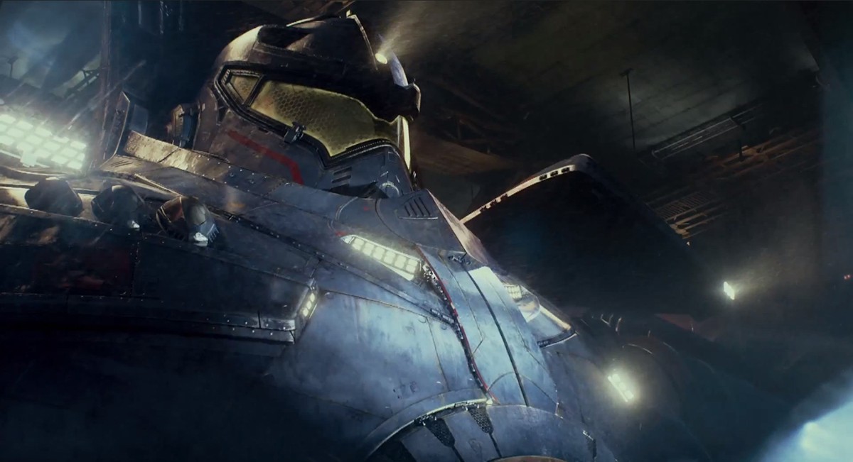


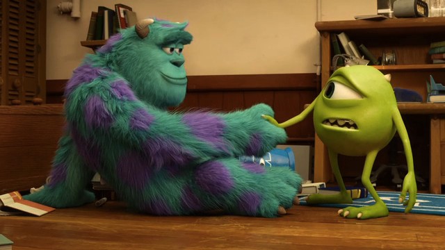

 The overriding trend at the moment is to move to a physically based shading and lighting model. Marcos Fajardo of Solid Angle – the company behind Arnold – remarked that every (production) studio in the world has moved over to being able to work this way or is in the process of moving now. “That is happening right across the industry, ever single company you talk to is either in the middle of it or has already moved, and this is something I have been working towards for the last ten years or so, so I am really happy to see that happening – finally.” Fajardo should be credited as one of the greatest advocates and enablers of this massive shift in the industry. Solid Angle is very much at the forefront of the industry-wide move to path traced GI with physically plausible lighting and shading in a production environment (meaning in a cost effective way with ever tighter schedules).


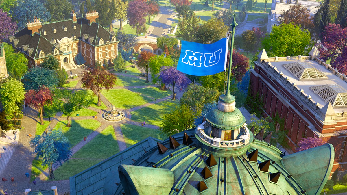

 Figure 1:
 Figure 3:
 Figure 4:
 Figure 5:

 Figure 8:
 Figure 10:
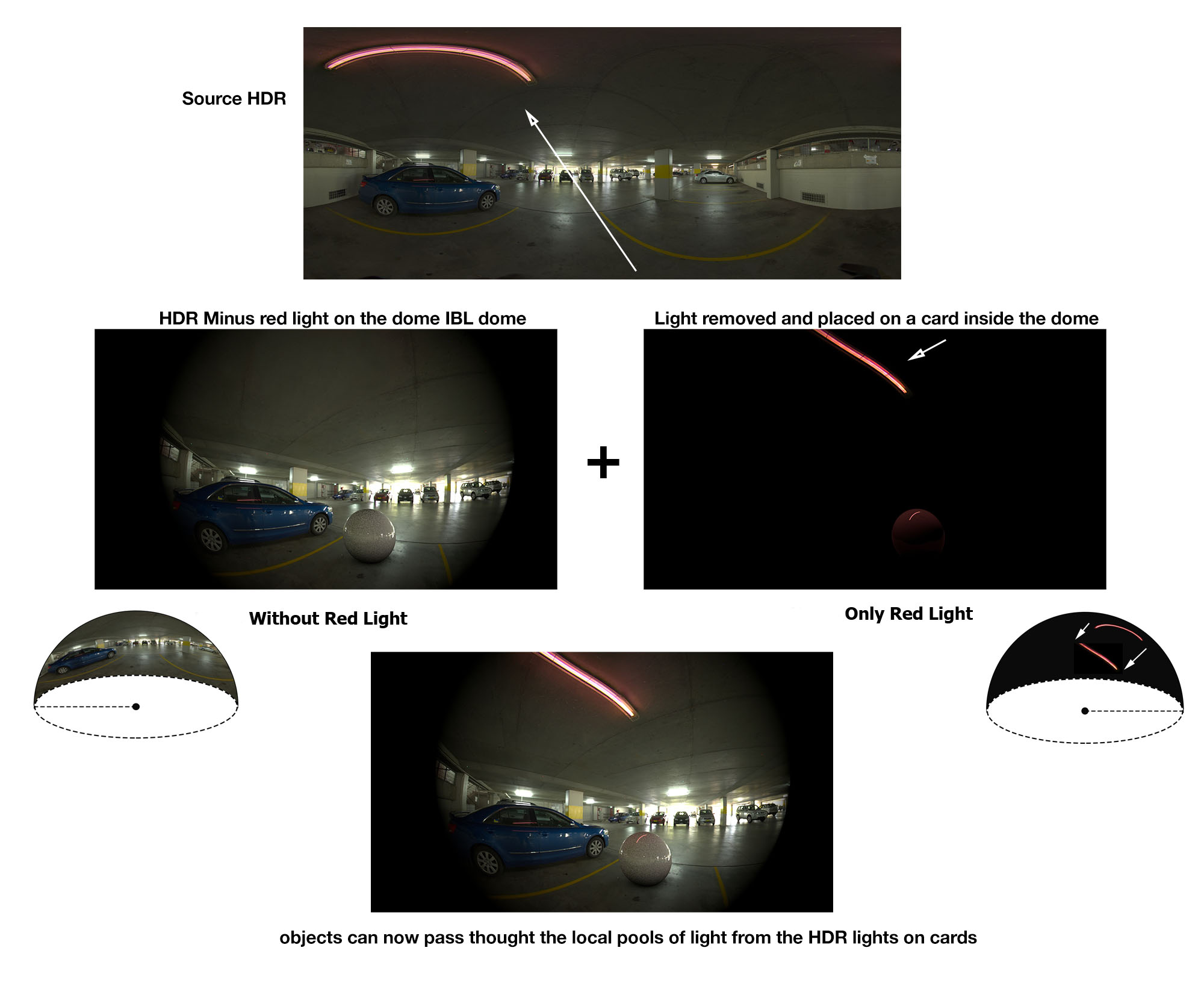


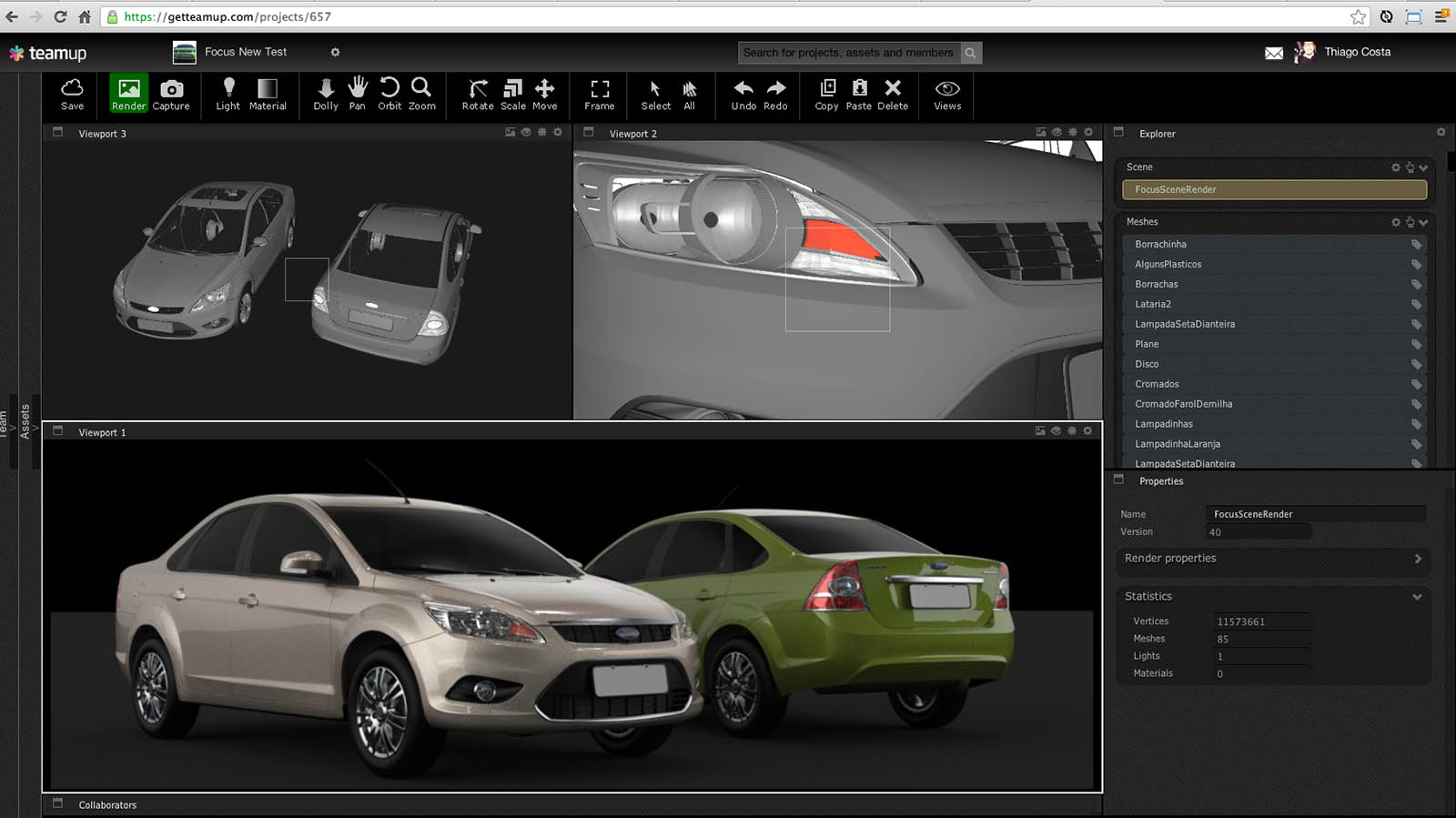


 Alembic has swept through the industry as one of the great success stories of open source. The baked out geometric process provided reducing complexity and file size and passed on a powerful but simplified version of an animation, or performance. All in an agreed standardized file format. It has been welcomed in almost every section of the rendering community. It allows for better file exchange between facilities and better integration and faster operation inside facilities. Since its launch at Siggraph 2010 and its public release at Siggraph 2011 (see our coverage and video from the event) both facilities and equipment manufacturers have embraced it.

 At last year’s SIGGRAPH in a special interest group meeting that SIGGRAPH calls “Birds of a Feather” around Alembic, Rob Bredow, CTO SPI asked the packed meeting room how many people used Alembic. A vast array of hands shot up, which given the steering role of SPI clearly pleased Bredow. It was not so much the same response from the same question on OSL. At the time Sony Pictures Imageworks used OSL internally and at the show Bill Collis committed The Foundry to exploring it with Katana, but there was no wide spread groundswell seen around say Alembic.
 An example outside Image Engine was shown by Ollie Rankin, from Method Studios, who presented at an earlier SIGGRAPH Birds of Feather on Cortex and how it can be used in a crowd pipeline. He had used a typical Massive pipeline which involved Massive providing agent motivation, and yet they felt Massive was not ideal for procedural crowd placement. In a hack for the film Invictus, they used Houdini to place the Massive agents, and they rendered in Mantra.


 OpenSubdiv is covered by an opensource license and is free to use for commercial or non-commercial use. This is the same code that Pixar uses internally for animated film production. Actually it was the short film Geri’s Game that first used subdivision surfaces at Pixar. See fxguide story including a link to the Siggraph paper explaining it.
I’m going to be pedantic but this is one of my big pet peeves:
” In other words if a light bounces off a table the bounce light would never be more than the light coming from the light source, and if one moves the light further away, then the bounce would not only seem less strong, it would actually reduce according to the inverse square law. ”
The inverse square law does not apply to every light. The inverse square law applies to omni-directional point sources. With an omni directional point source the photons expand on a sphere and therefore follow the inverse square law. If the photons though are focused in any fashion then they will not follow the inverse square law. For instance if you place a fresnel lens in front of a light or use a reflective half dome you get the traditional ‘par’ light. Moving a par light does not follow the inverse square law.
If an omnidirectional point light is a hand grenade going off and the fragments flying out in an even spreading inverse square pattern a focused light is like a shotgun with the density of fragments staying tightly grouped even after long distances depending on the ‘focus’. Similarly photons from an omnidirectional point light will spread out evenly. Photons from a focused spot light will like a shotgun blast stay in a tight grouping and not reduce in intensity.
The ultimate extreme is a laser. The photons from a laser are extremely parallel. It’s like the ultimate par light.
If lights couldn’t be focused we wouldn’t use them. We would just use a cookie cutter or flag on an open bulb.
A collimated or focused finite area light source will still follow the inverse square law (even if a laser does not) due to the area of the light itself following the inverse square law. As the light gets further away, it gets smaller, and therefore dimmer.
An imperfect focused spot light will get dimmer but not following the inverse square law.
If at 1′ your fresnel has a 2′ diameter and at 50′ your fresnel has a diameter of 10′ your circle of light won’t be 1/50^2 … 1/2500th the intensity. With a focused light you simply calculate the change in surface area. In this instance 1′ = pi luminance and 50′ = pi(10)^2 luminance (pi)/pi(100) = 1/100th.
Similarly if you put an egg crate to collimate an area light source the rays would travel parallel and the photon density wouldn’t spread (e.g. your intensity would remain the same). If you hit a flat surface with a high specularity they would stay parallel and you would get a caustic effect that also doesn’t ‘decay’.
Decay isn’t really decay except with atmospherics. Decay is just the effect of unfocused photons spreading out. Inverse square is really the ‘worst case’ scenario for decay in lighting. Which is good, otherwise we would need way more power in a flashlight to be useful. I see so many poor renderings though from people who assume inverse square is universal and a “law” and they apply it to everything from car headlights to flashlights etc without any discretion. And the resulting renders look physically incorrect.
*oops 1/25th. I forgot to divide the 10′ diameter by 2. So even less decay.
I googled “inverse square falloff fresnel” and found this page describing what happens with a fresnel lens:
http://www.portraitlighting.net/inversesquare_law.htm
You’re right, the lighting will not falloff with an inverse square decay as measured from the point source or the fresnel lens. However, it will falloff that way as measured from the virtual source. Interesting.
In the case of an egg crate, that will change nothing, however. That is simply collimating the light (blocking certain angles), not changing the falloff.
Oh, that page mentions a honeycomb grid similar to an egg crate, but their example included a mirror reflector which changes the focal length similar to the fresnel lens. I don’t think the honeycomb grid itself changes the falloff however.
An egg crate also doesn’t follow inverse square as I illustrated below. Yes it does, but each point sees more of the emission surface as it moves back, so the two cancel each other out. The net result is as if the light isn’t changing. http://i111.photobucket.com/albums/n134/im_thatoneguy/EggCrate_zps639df554.jpg
Thanks Gavin, yes it s true – that statement is a generalization that is not true for all lights, exactly. Thanks for that correction.
But as a note, lights are often focused to increase yield power to light. It is also focused to make the light controllable. And even a Dedo or real light like it must reduce with distance. Think of a patch on a dome. if the light is close the patch would be bigger – in an HDR the patch of the HDR that is the pixels that is that light is bigger… as the light moves away, that patch gets smaller, (just from perspective).. hence the light patch is smaller.
Mike
In an HDR wouldn’t the dome be at infinity? Therefore there would be no concept of “closer” or “further”. It would be purely directional. If you projected that HDR patch onto geometry then yes getting closer to that spot light projected onto geometry would give you the effect of getting closer to a perfectly diffuse area light. Which is, as you point out in the article, why ILM etc paint the lights out of their HDRs and recreate them in 3D so that they have proper focus, spill, flagging etc.
Oddly enough though I know of not a single rendering package that correctly models light falloff from a spot light. Every single package I can think of gives you “Linear, Inverse-Square, Custom”. It would be great if they automatically calculated the spread (and therefore decay) as you adjusted the focus. It’s not complex math even, everyone has just so bought into the “Law” part of the inverse square law that they mostly seem to have forgotten that it’s not a law.
light radius ^ 2 / (light radius + ( distance * tan( focus_deg / 2 ) ) ) ^2
Then we would just automatically get nice effects like this photo:
http://starcannonusa.com/wp-content/uploads/promotional-searchlights-runaway-country-2011-med-300×199.jpg
No sorry my point is if you were taking an HDR with say an 8mm fisheye, and you had a light close … took a photo and then moved the light away, it of course gets smaller.. this reduction in the actual size of the light in the fisheye frame shows the light falling off in a non linear fashion in a ‘dome’ style image. I was not trying to be mathematical just use it as a simple case to explain my point.
As always we really enjoy posts and comments so thanks again
Mike
Welllllll… no you wouldn’t necessarily. If we imagine for a moment a perfectly collimated light. 100% focused. Then in the fish eye would actually see an infinitely small dot of light anywhere inside of the lit area.
An egg crate on a soft box is an easier way to imagine it. As you get closer the “focus’ means you see less and less of the emission area. In fact as you move back you see exactly the same amount of the mission surface up to a point. If I increased this to an extreme level and made a very very fine egg crate at some point you would just see an infinitely small point of light.
Fresnel and spot lights are imperfect so there is enough spill to make the entire surface appear to emitting light but if you look at a sufficiently large dynamic range you’ll find that the emission surface of a focused/collimated light is constant. So to the human eye it does appear as if it’s just getting smaller and further away. But that’s because our eyes are clipping/flaring before the significant light source can be differentiated from the surrounding spill.
http://i111.photobucket.com/albums/n134/im_thatoneguy/EggCrate_zps639df554.jpg
Is that what IES profile is for? To recreate the Fresnel / Net patterns from imperfect physical light source?
you forgot our Artistic renderer! Pollock
http://www.bigman3d.com/pollock-renderer/
🙂
Great Article Mike, great to get a view on the bigger picture, love the religion analogy (Im a RenderManian)
Tom
“but it is very important to understand the move pioneered by ILM in removing or cutting lights from the ‘infinite’ distant dome and for interior scenes placing those HDR lights on cards in the physical space of the real world dimensions of say a 3D room”
Actually the idea of cutting out hdr lights and putting them on correct scale cards for energy conserving rendering was pioneered at Digital Domain for ‘The Curious Case of Benjamin Button’ 2 years earlier. It was presented at Siggraph 2009 in New Orleans at the The Foundry’s Nuke user group showing how the cards were cut out in nuke, the whole setup of the 3d environment exported to Mental Ray and how everything was checked in 2d using a novel animated hdr run through lightstage imagery.
If we don’t handle the anti-alias of color conversion, I mean, from SPH model to RGB model, how could we represent the all color of nature? I think this is the first step of phsically-based rendering.
Links of some pictures are broken, please repair