Ocula is at the very heart of the new post-production tools that have emerged to deal with stereo. Nuke and Ocula were used extensively on Avatar, and we explore the lessons learned with Simon Robinson, Chief Scientist of the Foundry. Ocula, in particular, is a real partnership between filmmakers on the cutting edge and the UK software developer.
Ocula is a specialist tool from the Foundry for dealing with stereo production. Ocula version 2 came out at the end of last year. Each Ocula release has been linked to a Nuke release.
Ocula is very much a work in progress, such is the state of stereo post-production. So new is hardcore visual effects in stereo, and yet so in demand after the massive success of Avatar, that Ocula is one of the hottest programs on the market and one of the most technically least understood.
Weta used Ocula substantially on Avatar. So what is Ocula and how does it work? And just how useful was it on Avatar?
Before discussing how widely it was used on Avatar, it is worth noting how useful Avatar was to Ocula.
Filmed stereo material can exhibit differences which can lead to eye-strain. These differences can comes from multiple sources, for example:
• Paired cameras on a rig need to be carefully aligned to avoid vertical disparities through misaligned camera geometry
• Mismatched zooming
and interestingly
• Keystoning effects from converging camera rigs

James Cameron is one of the world’s greatest exponents of shooting stereo converged. More than any other filmmaker, he has led the charge to always film with the cameras slightly pointed in and aimed at the centre of the action.
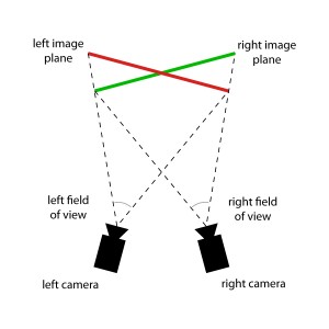
Prior to Avatar the assumption had been that Ocula would be needed to address the camera keystoning that occurs when you have two cameras converged (pointed in on each other or ‘toe in’ as it is sometimes referred to). Simple converging of the two viewing pyramids of each camera which are at a slight angle to each other will result in an image plane where the left eye is a bit taller on left of frame and the right eye is a bit taller on the right. Imagine projecting two video projectors at a wall – if you moved one to the left and one to the right and yet pointed them both at the same centre point – you’d expect cornerstoning on each image. Of course this means, on paper anyway, that the sides of any stereo production filmed using the Converged or ‘toe in’ technique, will have poor alignment at the edges.

Alignment is one of the key areas, therefore, that the Foundry have been focusing on with Ocula. “In reality,” explains Simon Robinson, “very subtle camera misalignments almost always dwarfed all the camera keystoning effects – certainly for fairly narrow camera separation on reasonably well set back filmed subjects.” As such Ocula 1 was targeted at keystoning whereas Ocula 2 has benefited from the real world forge of production and thus is much more focused on fixing and correcting for subtle camera misalignments. “That was the one thing across the board that (early adopters) found, and I think today it is still the number one issue that people need to solve in terms of their workflow,” says Robinson.
The Ocula 2 alignment tool will now correct for:
• keystoning (it will adjust for a vertical offset: in your head your left eye is always – always – fixed level to your right eye – skulls are very rigid bones)
• it will also correct for a nodal move on one of the cameras (although in reality an actual nodal pan of a camera is highly unlikely as the most common pivot point of the camera is the base attachment to the camera plate which is well back from the actual nodal point of a lens)
Correction may appear a trivial problem but it is far from it. At a maths level for just a nearest best approximation solution, it is assumed that adjustments are nodal (rarely prefectly true) and the cameras are at least mounted in an imaginary horizontal plane. When one considers that on most rigs the actual cameras are mounted at 90 degrees to each other with a mirror – even this base assumption is far from a given.
At the heart of the technology to solve stereo problems is the concept of a disparity map. About half the tools in Ocula are built on the technology of the core displacement map. The other half of the tools work on feature mapping between the left and right eye, a relatively sparse pattern match between left and right eye (sparse compared to a per pixel disparity map) and on frequency and colour analysis.
Disparity Map
 Any image is a two-dimensional (2D) representation of a three-dimensional (3D) scene, which by definition will contain elements, actors and props at different depths from the camera. In an image taken from a slightly different viewpoint – i.e. the second camera on a stereo rig – the same elements will appear slightly shifted due to parallax. Stereo disparity is the term used to describe the shift that occurs for a particular point in 3D space between the left and right images. In a stereo pair, the cameras are offset horizontally, so in a perfect world this would be a purely horizontal shift. The amount of the shift varies with distance from the camera and can vary pixel to pixel. In addition, one eye may see areas that were not visible to the other eye.
The key, from Ocula’s point is view, is to assume that both images were captured exactly at the same moment. So any shift between the left frame and the right frame is NEVER due to anything moving or being in motion, but ONLY due to distance from camera. Furthermore, it is not even possbile to assume that the distance between the two cameras is the same from one frame pair to the next. This is not always true – even ‘rigid’ rigs flex during a shot, so for most shots it is assumed not to be fixed. But one improvement from Ocula 1 to Ocula 2 is that instead of assuming they are completely unrelated – the distance between the cameras is slowly merged or animated from one value to another – allowing key frames means that another source of jittering can be removed. So regardless of whether the shot is dynamic or not – it is assumed the tiny distance between the lens moves from one value to the next rather than jumping around erratically producing noise.
The Ocula software can build a picture of the stereo disparity by estimating the change in position of every point in the scene between one view and the other. In a method very similar to optical flow – but unlike optical flow – a few more things can be assumed to be known or fixed and most importantly nothing is moving between what is seen by the right and left eyes, they are both snapped at the same time.
In short – Ocula works out a ‘depth map’ on the layout of the scene. Once this map is created – one eye can be adjusted in very complex and useful ways in three dimensions – rather than just as a simple 2D transform or distort. These 3D adjustments produce vastly superior results and are on par with camera mapping, or projecting the scene back down on a rough model of itself, and then adjusting the digital camera’s position or photography and recapturing.
“Most of the core algorithms got rewritten between Ocula 1 and Ocula 2,” comments Robinson. “One of the key algorithmic things was to improve the disparity map generation between the two – and that is massively better, and second thing was to improve the workflow, with the benefit of real world experience (from Avatar) we learn a lot about having more control and just what was needed to make this work. A large part of the reworking of Ocula 2 was workflow, for example, every effects shot has a camera solve for it and so there is little point in that feature film workflow, for Ocula to re-do all that – we should instead inherit that work (tracking data) that may have already taken several hours to achieve a good track.”
Under the hood the Foundry uses two different algorithms to generate their disparity maps. One is a variant on their highly successful Kronos optical flow approach but with the higher stability of having variables that stereo so generously provides. The second algorithm is a dynamic programming technique, which is a method of solving complex problems by breaking them down into simpler steps. (This is unrelated to computer programming – but rather it is a problem solving approach that is often implemented with recursive algorithms).
A third algorithm is currently being explored to improve the frame to frame or “temporal stability” of the disparity maps. This research looks extremely promising but at the moment is still computationally expensive.
Today Ocula 2 is still open to some temporal artifacts, such as noise or jitter frame to frame but as Robinson points out, “This stuff is very far from done, and what we are developing next is a lot more temporal consistence in the disparity fields, and a lot of this is being driven by wanting to make it better – but we also have customers doing some really interesting things and going to the next stage, especially extracting depth information from stereo shots – and having z-depth for each eye and partial geometry reconstruction.”
Disparity estimation is a well-explored topic in the research community, with many papers being published in the last ten years highlighting a variety of approaches. The disparity maps can be used to map the world in 3D space in much the same way as a 3D tracking/camera solving software does – in fact both can use epipolar geometry triangulation to work out the depth map of the world in front of the lenses. All points then in the scene can be mapped to follow the calculated Epipolar lines. In fact you can convert from a disparity map to a depth map, if you know the camera calibrations and rig geometry – or in other words, if you have a stereo camera solve.

Color
Color differences between the two views of a scene can also make it more difficult for the viewer to resolve objects, actors and scenes successfully. The problem is most camera rigs cannot move the lenses of the actual cameras close enough due to the physical size of the lenses and cameras and so a beam splitter/ mirror rig is used. This allows cameras to film on top of each other and yet capture footage a sensible interocular distance apart. The problem with mirrors and this approach is that each mirror or glass inherently acts as somewhat of a polarizer – making the image seen from each lens different enough that the footage needs to be digitally adjusted back into alignment.
The issue is that not only can the glass tint the image but it happens in varying levels to different areas of the image – so typically the blacks may have a greenish cast while the appearance of highlights can be significantly different between the left and right views.
ILM solved this by detailed manual matching and color grading of the left and right eye material, while Weta used Ocula to try and automate the process. Initially Ocula 1 used matching technology that could vary between frames and produce flicker. While the computer matched each pair of frames – it did not match forward or backward with respect to the clip – so the stereo pairs were made to match but this adjustment varied frame to frame – leading to flicker.
“We did a lot of work on this – and a lot of this colour matching in stereo was informed by ILM -and I have to say as a result now with Ocula 2 the color matching tools are the second most widely used and valued tools with Ocula customers worldwide,” explains Robinson.
Unfortunately, just one global offset or adjustment is rarely enough. Ocula 2 now not only allows masking but also regionalized color grading based on disparity maps. The Foundry now has other new customers that are pushing this area of Ocula 2 due to specialist shiny wardrobe and thus specular highlight issues that are driving this research beyond even the pressures of Avatar. While not committing to anything absolutely, Robinson thinks this will be one of the next areas of published improvement within the Ocula code – perhaps as soon as the American Summer.
The problem can be understood if you imagine a stage with a shiny floor, or say a still pond or pool. One eye (camera) is seeing the actor reflected in a still water of the pool, and the other eye(camera) sees no such reflection due to the polarizing effect of the mirror. One eye sees the full reflection – and in the other it is missing. Another example is a rich blue sky that appears to have been shot through a very heavy polariser and is thus dark and saturated, while the other eye appears to have absolutely no polarizer at all and, while the clouds look the same, the sky is vastly different between the two eyes or cameras.

Robinson points out that the key to both Ocula and setting up a stereo workflow in general is to be as flexible as possible. “Everything is far from a done deal…and it is interesting how even all the companies that worked on Avatar – all adopted different workflows… where did you do your lens distortion correction? who does the 3D tracking? do you give your artists corrected plates? what camera settings do you render with? – etc. – there is just no “one way” to get through this – no one “correct way” to do things – a flexible approach is the only way to go. On an unrelated point, there is not one post house we visit now that does not want to discuss or explore stereo – and if we can credit Avatar’s success for all that – so be it – but I feel its going to be a very busy year.”
Images copyright. 2009

Pingback: Art of Stereo Conversion: 2D to 3D – 2012 | Light Iron