Texturing is central to 3D. From UV to UDIM to Ptex, it is easy to think one technology has just displaced another, but the reality is more complex. UDIM UV mapping has enormous popularity for texturing in the face of much newer systems such as Ptex (which works very well in its own right). While Ptex may still yet win the texturing heart of pipelines around the world, it has not yet become the dominant force.
Ptex
The Disney Ptex library became available to the public community of texture artists, lighters and modelers about four years ago. It was in June 2008 that Ptex was first presented at the Eurographics Symposium on Rendering by Disney Animation, and later that year that Disney’s Bolt was released; the first feature film to use Ptex. By September of 2009 Ptex was integrated into Pixar’s RenderMan Pro Server 15.0. and then at the start of 2010 Ptex released as free open source. Many including this author assumed it would sweep the texturing community. While it is still very much alive, it is UDIM texture encoding that appears popular amongst studios large and small. We set out to find out how this simple yet powerful texture co-ordinate system has flown under the radar and established itself so firmly in pipelines around the world.

Ptex vs UV
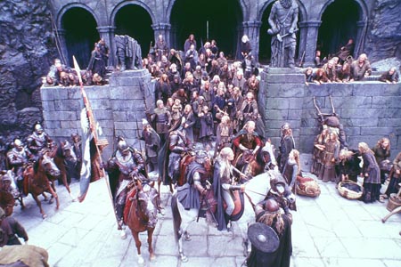
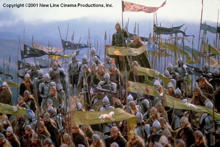
Ptex addresses many issues by eliminating the need for UV assignment, providing seamless filtering, and allowing any number of textures to be stored in a single file. It holds the promise of more efficient memory use, and a solution to unfolding and flattening issues common in UV mapping. Yet while it is popular in some companies, many pipelines use the UDIM method increasingly, a system invented by Weta Digital at the time of the film The Lord of the Rings: The Two Towers in 2002!
Background on Ptex:
- it is great at packing a million files
- Ptex at its lowest level is a file format
- it came from Walt Disney Animation Studios (the format is 4 channels, 8 or 16-bit integer, or float)
- It works if you have a render which understands the Texel data (eg RenderMan, V-Ray, Maya Hardware Render 2.0, and Maya mental ray (using the mib_ptex_lookup node), Mantra, Air, etc)
- (fairly) widely adopted
- not perfect (multi-threading)
It is this last point that has caused people such as Arnold founder Marcos Fajardo to not advocate its use. (See fxguide’s State of Rendering Part 2).
EXTRACT: “You would be surprised”, explained Fajardo, “even Disney’s almighty Ptex library, which caused so many ripples in the industry, is not threaded well and destroys the performance of your renders. Which is probably OK for Disney as they use PRman therefore running it on very few threads. But run it on all the threads of a powerful machine, as we did, on a simple scene with a single Ptex-textured polygon, and the results are abysmal.” Here are the results Solid Angle provided to support this claim:
threads pixel rendering time speedup 1 18.94s 1x 2 11.91s 1.6x 4 7.23s 2.6x 8 9.44s 2.0x 16 12.37s 1.5x 32 13.39s 1.4x 64 14.65 1.3x In this test case, instead of 32x faster with 32 threads, it’s only 1.3x faster. “Which means that 30 of the cores are idle and you are wasting your money,” he adds. …
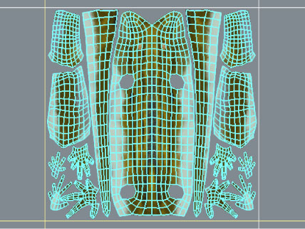
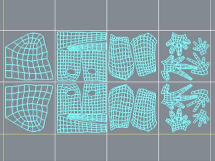
The move to Ptex is driven by issues with taking a 3D ‘skin’ and flattening it to a 2D flat representation – traditionally as a UV mapping. Namely that:
- faces don’t flatten nicely, this is inherent with a 3D surface in a 2D world
- the desire for uniform texel density
- ideally not having wasted space as in a traditional UV mapping – where large areas are blank
- simply not having to worry about UV mapping, with its creasing, seams etc
- not having to worry about changes of density so the texture is not even over the shape
- the desire for very good memory management
None of this has changed or is untrue, but the industry has not really wholeheartedly adopted Ptex:
- UDIM is very popular
- UDIM is fast, allows paint over of stills, which can still be more efficient (esp. for quick fixes)
- Ptex is not supported by everything (eg from Mudbox to MARI and everything in between)
- Ptex can be limited to 8k x8k UV’s say 32k x 32k in Arnold
- Ptex’s require you to have a pretty much locked asset before work can begin where as UV’s can be much more forgiving
- If you don’t have enough tessellation in your geometry you can’t get enough resolution in Ptex
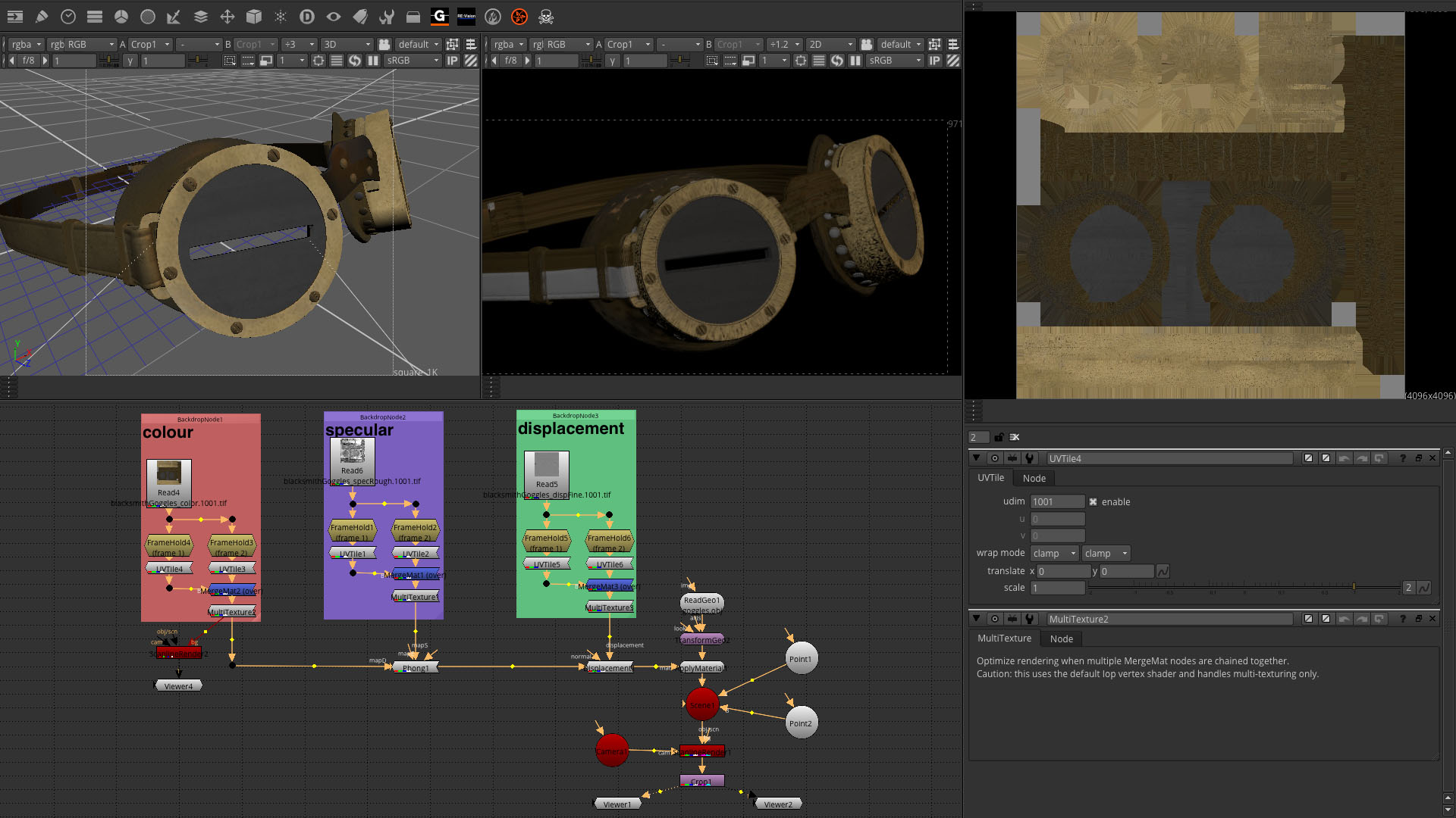
UDIM is not new – it was invented by Richard Addison-Wood and came (as many good things have) from Weta Digital (circa 2002). It comes from U-Dimension numbers 1001 upwards. The system of parsing UDIM files is really easy as the order is embedded into the very filename in a really easy to access way. Using other naming system like like u0_v0 naming requires a bit more parsing. In a word it is simple. As such major companies like MPC, DNeg, Weta Digital and others use it daily.
MARI, also originally from Weta, naturally supports UDIM natively as that was the naming convention in use at Weta Digital when MARI was written. MARI when it was moved to The Foundry in the UK would be extended to support Ptex but not at the cost of supporting UDIM. Many people including fxguide expected that a MARI-Ptex solution would prove overwhelmingly popular, and yet a MARI UDIM texturing pipeline remains very much one of the most popular options.
Many games companies use Atlases for texturing. The Atlas approach has traditionally been a system chosen in games. This system takes all the textures for the assets and puts them into a single UV tile (0 – 1). It is not natively possible to work that way out of Maya or 3ds Max but there are a few plugins available to help – it is a very viable alternative to both UDIM and PTex. RenderMan Studio, for example, supports MARI UDIM and Mudbox Atlas textures referenced via Maya’s Image File node (the rmanImageFile node does not support these indices at this time).
What is UDIM?
“Some people swear by PTEX or UDIM and others swear at it.”
– Senior texture artist
UDIM stands for U-Dimension.
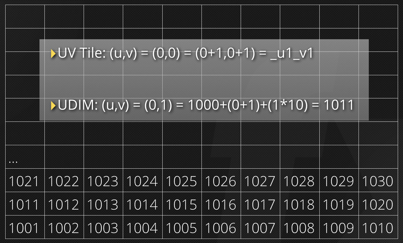
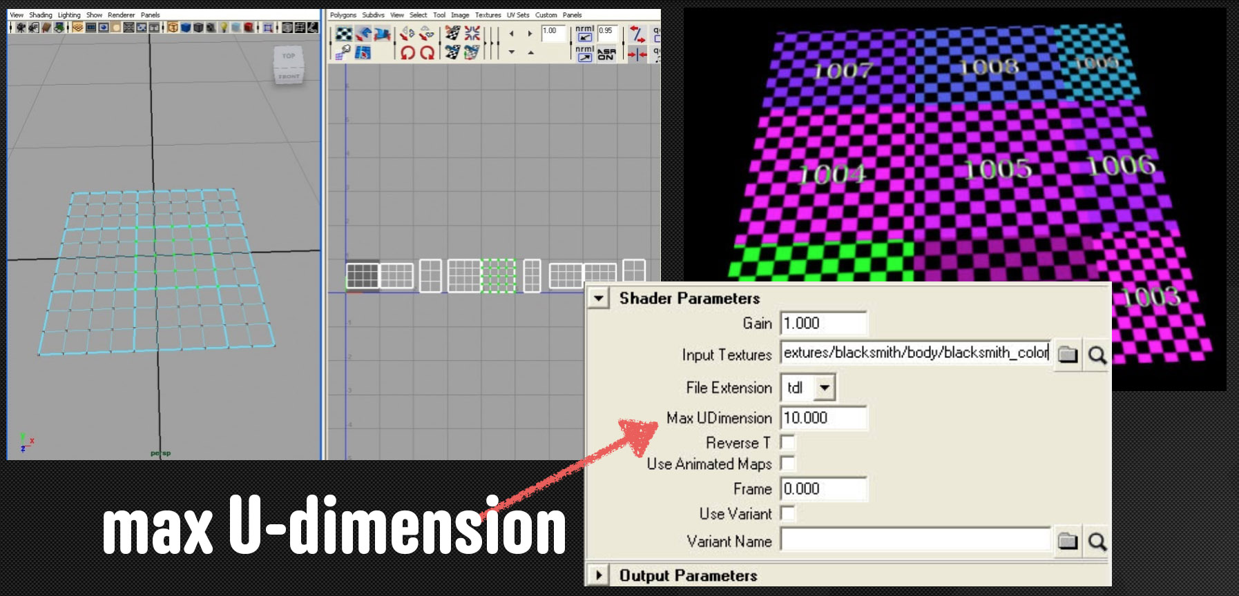
UDIM is a way of creating a single linear number that identifies each integer block in UV space. You do this by defining a limit on the number of patches you can use in the U direction (the U-DIM) and then resetting U to 0 and incrementing V by one after reaching that number. i.e. fill in all the patches up to U=10, then go back to U=0 and go up a line in V. In fact, while UDIM could use an U base number, 10 is now the default and almost exclusively the only number used.
The UDIM number starts at 1001 with the U=0,Y=0 being 1001.
In the early days the value of UDIM was not fixed. Arbitrary values could be picked depending on the asset in questions. A UDIM of 40 would mean you go 40 patches over before going up to the next line. Not long after implementing the system the Weta Digital texture team itself standardized on UDIM=10 which is what is hard coded into MARI.
UDIM has a bunch of benefits.
Firstly, parsing UDIM embedded into a filename is really easy, using a different scheme like u0_v0 naming requires a bit more parsing.
Diffuse.1001.tif vs Diffuse.u1_v1.tif
Secondly it makes processing texture sets in NUKE (or Shake when it was invented) really easy as they form an image sequence that can be handled with a single file-read node. This is useful when you have 500 textures for each channel.
Symmetry schemes can be easily implemented. If you decided that all left hand side textures start at 1001 and the symmetrical textures are offset by 200 you can find the symmetrical texture for any given UDIM simply by RightHandTexture = UDIM + 200;
Weta Digital: the design history
We spoke to Richard Addison-Wood, senior software developer at Weta Digital, and the father of UDIMs about the history and initial design of the system.
fxg: When was the first UDIM system invented and by whom?
Richard Addison-Wood: The system was created in early 2002. My recollection is that I proposed the representation. The kernel of the idea was probably raised in some meeting when we were discussing the limitations of the representations we were already using. With my deep understanding of the IEEE floating point representation, I knew the sort of limitations and trade-offs we would need to be aware of with regards to encoding additional information in UV coordinates.
At the time, we were in the process of switching from using nurbs patches to subdivision surfaces for our creature models. One of the representations we used early was to use Maya’s Shading Groups. All the faces meant for a particular Map ID would be placed in a shading group whose name incorporated the Map ID. We also had used a scheme where there was an additional dynamic attribute attached to each mesh that held the Map ID for each face.
The proposed scheme we decided to put in place was meant to reduce the reliance on auxiliary data for recording the Map ID information.
On March 20, 2002, I installed one of the necessary tools for putting the system into place. For what it is worth – we had the desire to support bilateral symmetry. So the texture with Map ID 1001+n would be on the left side of the creature and Map ID 2001+n would be the corresponding texture for the right side.
fxg: The first system has arbitrary U bounds before it goes to the next V line – could be 10 or some other number – did that ever get used? How did you know how to read the file? Was there some heading info?
Richard Addison-Wood: We stored additional attributes on our meshes the recorded the information. Originally, the additional attributes were rmanFudim, rmanF__mapBaseLeft, and rmanF__mapBaseRight. We eventually renamed rmanFudim as rmanF__mapUDim.
The rmanF__mapUDim attribute recorded how many tiles to have in a row before moving to the next row.
We often set rmanF__mapUDim according to the texturing needs of a particular model. We wanted to make sure that the number of tiles in a row was about the same as the number of rows. If rmanF__mapUDim is too small, you can end up having too many rows, with the corresponding larger values in V. As the values in U or V get larger, you lose the precision available for representing differences in UV coordinates.
fxg: The current UDIM is central to MARI – which came first, the UDIM or Mari’s implementation at Weta? Or was there Shader implementations etc and then finally Mari or did Mari lead to the 10 standardization?
Richard Addison-Wood: My understanding is that Martin Hill suggested that we lock rmanF__mapUDim to 10. That choice makes it easier for users to look at UV assignments and determine the corresponding Map ID in their heads.
However, by locking rmanF__mapUDim to 10, you can end up growing too far in V and losing some precision the V coordinate.
fxg: Why start at 1000?
Richard Addison-Wood: Back when we did our creature models as collections of nurbs patches, our texture Map IDs started at 1001 for the left side of the creature, and at 2001 for the right side of the creature (when the was reasonable symmetry).
The main reason to start at 1001 (or even 1000) is that the numbers we end up with is 4 digits (at least when the number of Map IDs doesn’t get too large).
This has some convenience for various other parts of the pipeline when they are forming the filenames for each texture tile. There is some convenience in having the same number of digits for representing these numbers, and by starting at 1001 (or 1000) we avoid having to pad the numbers with leading zeroes.
The fact we had started using 1001 rather than 1000 was probably just the choice of the guy who handled some of that early stuff for us in the Shaders Department.
fxg: Has the 9999 limit ever been an issue at Weta? One assumes you would just break it into sub files?
Richard Addison-Wood: In practice, the loss of precision in V would likely be noticeable before we ended up with 9999 tiles.
I think there are also some practical issues with having so many tiles. Typically, you would want to balance between having enough different texture tiles for having control of the different resolutions you want for different parts of a model and having few enough that things are still manageable.
fxg: Why not just _U#_V#? What was wrong with (u,v) in the first place?
Richard Addison-Wood: That would certainly be a reasonable alternative. However, there are many tools where it is indeed very handy to have one number for the Map ID.
We have long had tools for listing directories that would summarize a sequence of files with an image or tile number in them. This is also quite common in file dialogs for programs that deal with image sequences.
fxg: I assume the linear naming makes it much better for a NUKE style file read-in?
Richard Addison-Wood: Yes, this is an example where it is helpful to have the Map ID represented as one number.
fxg: As I read somewhere, why not something just like int(u) * 1000 + int( v )? and the numbers range to 999,999 (again I guess it is a file reading issue?)
Richard Addison-Wood: That is basically what you would get if you set rmanF__mapUDim to 1000. However, as a practical concern, if you started using values in U that got up near 1000, you would have very noticeable lose of precision in the U coordinate.
If you avoid getting too large in U or V, that scheme starts looking like the _U#_V# idea (discussed above). The difference is that there would not be any text separating the U and V parts of the number.
Note that when the image or tile numbers start getting fairly large that many of the tools that handle sequences of image or tile numbers might choose not to treat those as sequence numbers. In many places we use 6 digits to represent dates, so we often ignore numbers with more that 5 digits when handling image and tile sequence numbers.
fxg: Why has UDIM-UV been so popular vs Ptex. Why go UDIM-UV and not Ptex?
Richard Addison-Wood: I think that Ptex is really a great idea.
However, there are a number of practical concerns with switching a pipeline over to using Ptex. Furthermore, texture artists are quite used to working with UV maps. Yes, that requires the additional stage of assigning appropriate UV maps. However, we do make some very deliberate choices about how we lay out our UV maps which means that many things we want to do with textures can be done straight in UV space.
I think that the popularity of UDIM is that it is fairly easy to understand and to implement. In many ways, it is a fairly obvious approach.
All this means that it is easy for someone who is already using UV maps to adapt to using UDIM.
Thank you to Richard Addison-Wood, Weta Digital, Will Earl and Matt Leonard & Wayne Robson (fxphd.com instructors and 3D artists) for their assistance in producing this article.
Images used LOTR : 2002 New Line Productions, Inc., The Saul Zaentz Company, Tolkien Enterprises under license to New Line Productions, Inc. All Rights Reserved. fxguide LLC.
Pingback: I produce with UDIM UV mapping | Audio Video
Great article, I love the depth of these features.
Very interesting point raised here, we have found that for things like fabric textures, it’s useful to have the surface parameterized the way we get with UVS, as it’s analogous to the way a tailor would create 3d clothing from a 2d pattern. The UV seams fit perfectly with the way a tailor would place fabric seams.
I’m not aware of a nice way to do that with the projection methods we’d have at our disposal with ptex.
I hate being this guy, but I just wanted to point out a simple mistype. Feel free to erase this message after you fix it.
The First Lord of the Rings: The Two Towers image, has the caption “Lord of the Rings: The Twin Towers”.
Pingback: UDIM UV mapping | ila.solomon
Pingback: Виртуальный Техникум
Great read, super informative.
Pingback: Embedding 3D models into websites – Korey Rosenbaum
Pingback: ANM220.1 Wk08 | Lola Koha
Awesome article! Great information here!
Pingback: UDIM UV mapping | CGNCollect