Dynamic Projection Mapping
You may have seen this video on the net – it’s remarkable dynamic tracking is worth seeing. The video shows a rapid system for reading non-rigid surfaces, solving them and then projection mapping an image on them.
The video is part of an IEEE paper called Dynamic Projection Mapping onto Deforming Non-rigid Surfaces Using Deformable Dot Cluster Markers, and this is how it works.
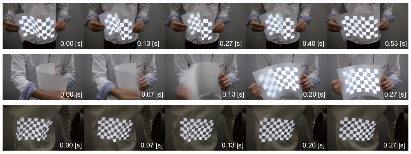
It is important to note, as is briefly explained in the video, that this is not a general purpose solution, as it requires a pattern to be applied to the target material. This pattern however can be applied using ink that can only be seen under infrared light. The system operates with a special projection and display technology that runs at up to 1000 fps, allowing for the target object to move with the projected image seemingly perfectly tracked onto it without any lag or latency, especially when the resulting solution is filmed (as above) at 30 fps on a normal camera.
Projection mapping has gained great attention in recent years especially in the area of large scale building overlays such as animations on the sides of public buildings. Companies such as Microsoft have also made significant advancements with feature tracking in the areas of Mixed or Augmented Reality (MR/AR) headsets. The Microsoft Hololens, for example, has exceptional tracking. But the Hololens or even less advanced AR with overlays of graphics on camera input from an ipad, require the image to be viewed via a device, and the overlays are seldom dynamically mapped to non-rigid bodies. Projecting moving clips onto moving objects, without the need for an independent device, is known as Spatial Augmented Reality (SAR).
Gaku Narita, Yoshihiro Watanabe, and Masatoshi Ishikawa in Japan have developed a SAR system they call Deformable Dot Cluster Marker (DDCM), this is a new marker approach for high-speed tracking of non-rigid surfaces using a high-frame-rate camera.
The team is part of the Vision Architecture Group at the Ishikawa-Watanabe Laboratory in the Department of Information Physics and Computing at the Graduate School of Information Science and Technology, University of Tokyo. The Vision Architecture research group aims to make major contributions in a variety of application areas by exploiting high-speed image sensing which is beyond the capabilities of the human eye. “We create various applications in the fields of robotics, inspection, video media engineering, man-machine interfaces, and digital archiving by making full use of VLSI technology, parallel processing, measurement engineering, and computer vision” the team explains on their web site.
Their DDCM has three performance advantages.
- It can detect the shape, even when it is strongly deformed;
- It provides robust tracking even in the presence of external and self occlusions; and
- Finally, it is very fast, providing millisecond-order computational speed.
Using their approach, of DDCM with a high-speed projector, they can projection map so it appears the animation or still image is “printed” on the bending paper or piece of clothing. Applications in theatre, fashion shows, entertainment and even interior design are just a few obvious applications. One can imagine seeing a stage show where the costumes are changing during the performance, without the need for special glasses or needing to view the stage at a precise angle (especially if multiple synced projectors were used).
Image detection
The process of computer vision works like this:
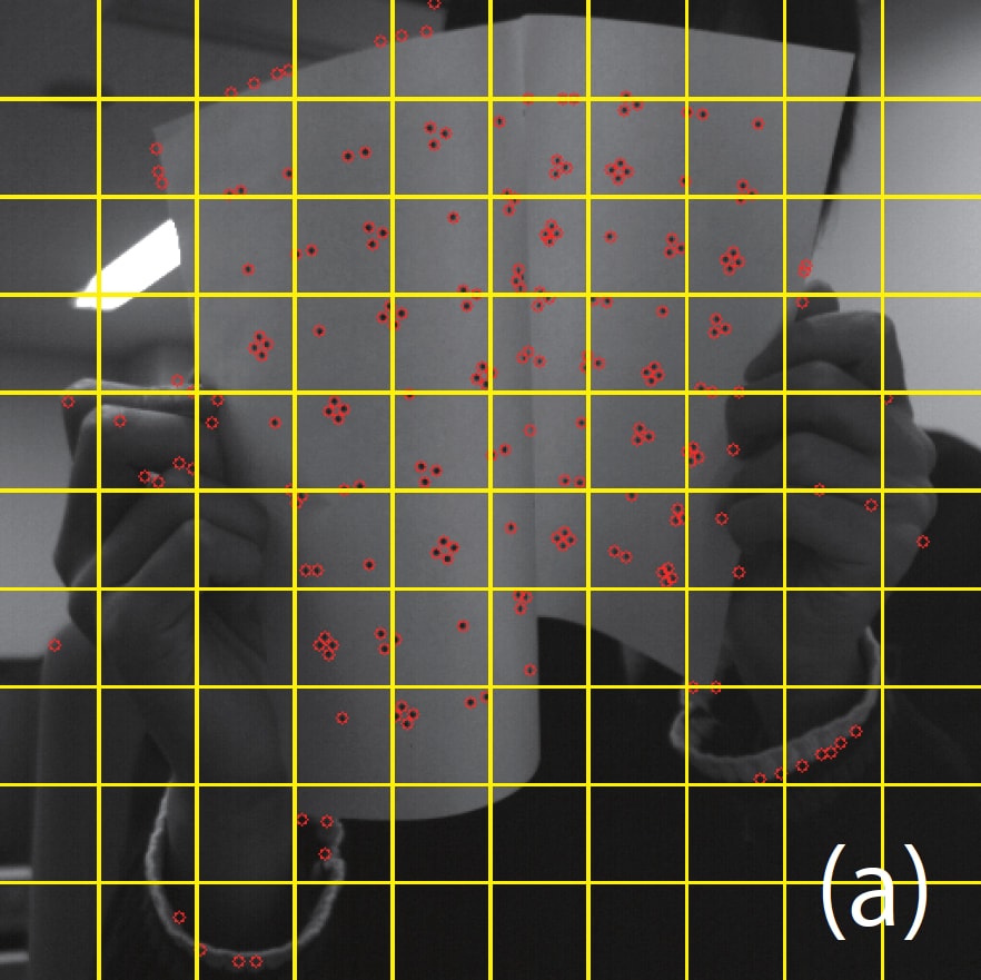
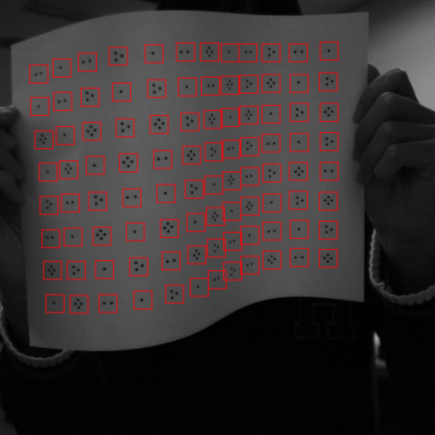
Keypoints are extracted from the high speed camera image. Note that in the image the points are not just identified but the machine is seeing either 1, 2, 3 or 4 point markers, as in the print pattern.
These 1,2,3 or 4 point dot clusters are interpreted as the right type of dot cluster – above all the 3 dot clusters are blue, all the 4 dot clusters are yellow etc…
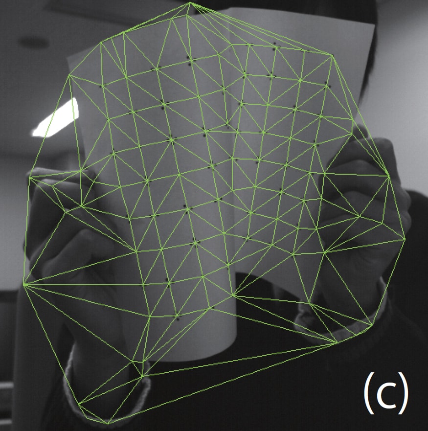
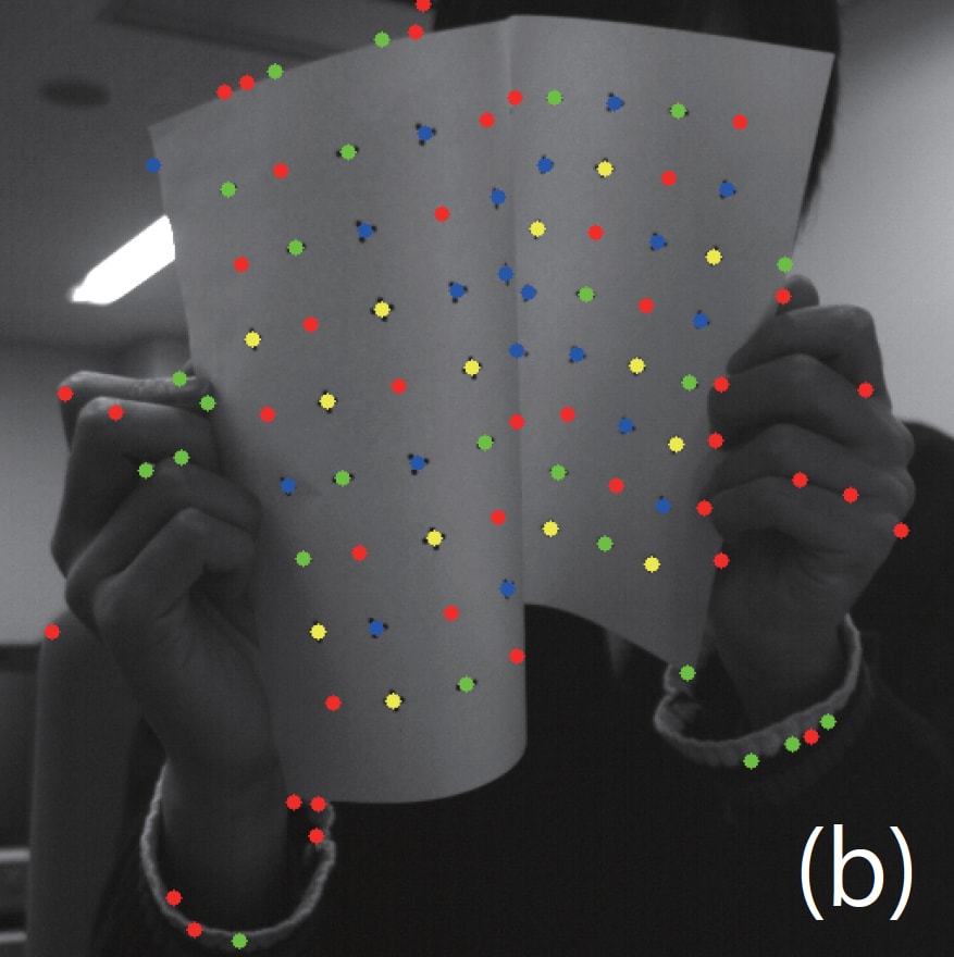
(c) Shows a ‘Delauney’ triangulation for extracted dot clusters.
A Delauney trangulation is a way of producing triangles such that none of the found points are inside the circle drawn around of any of the triangles. Delaunay triangulations maximize the minimum angle of all the angles of the triangles. In other words, they tend to avoid ‘sliver’ triangles. (The triangulation is named after Boris Delaunay for his work on this in the 1930s). Readers might be familiar with Voronoi diagrams from common destruction simulations. If you take all the circles in a Delauncey Triangulation and connect the centers of the circles it actually produces a Voronoi diagram. The two concepts are completely related.
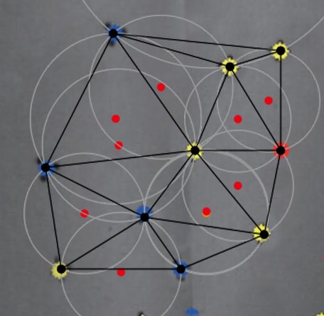

(NB: In the images below the yellow and blue dot clusters are used to form the triangles, which then define the circles. At the centre of each white circle is a red dot. Connecting these centres would give a familiar Voronoi diagram. But there is no need for a Voronoi diagram, it is the Delauney version that is used in the DDCM.)
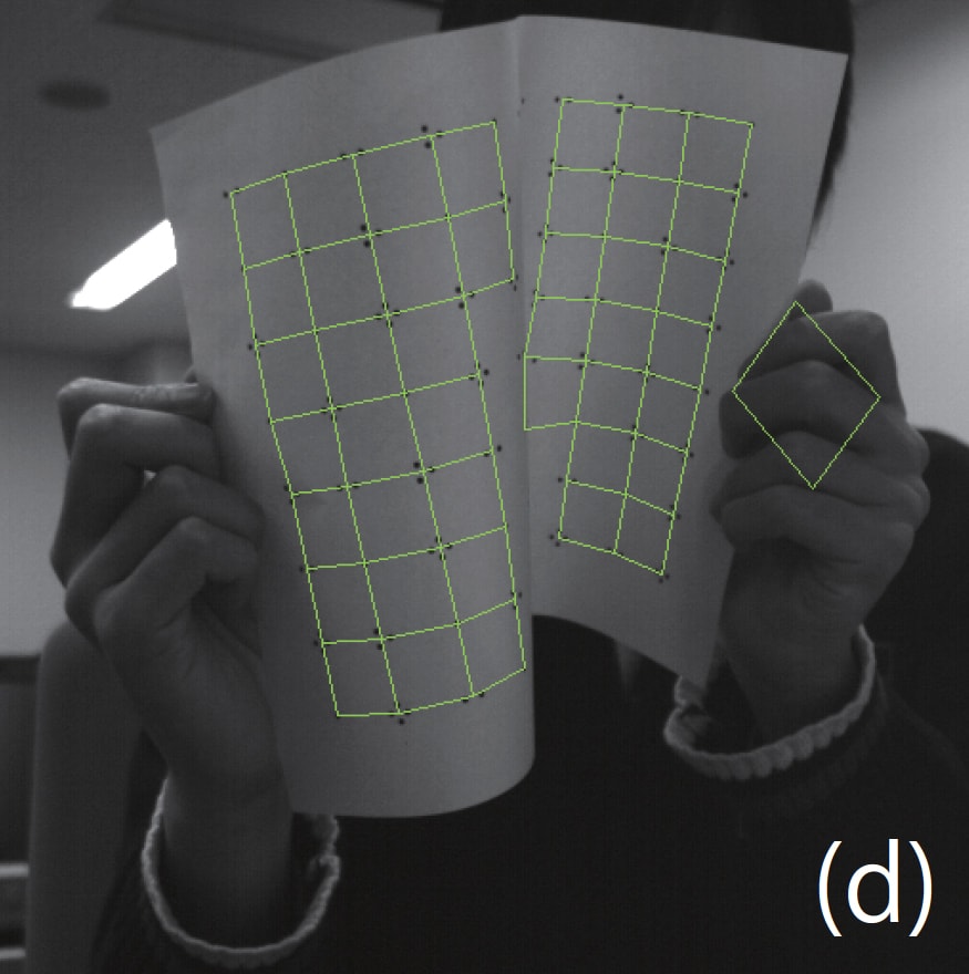
(d) The connectivities among dot clusters are obtained based on the breadth-first search.
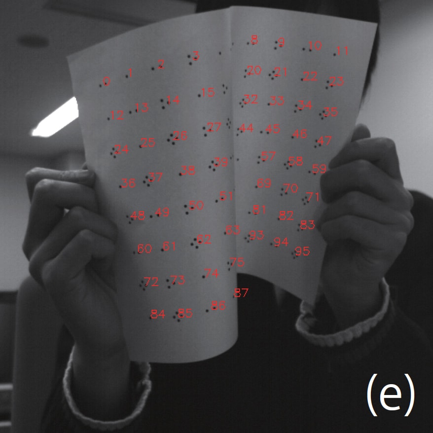
(e) Finally the IDs of each dot cluster are identified based on dot numbers by the known table of the pattern. The red numbers in (e) represent IDs of identified dot clusters.
The process now knows what it is looking at, but still only as a flat plane. To create an accurate projection it needs to have a 3D surface that it can use to project the right ‘distorted pattern’, such that the viewer believes the pattern was distorted by being printed on the non-rigid object (and not inside the computer).
Tracking
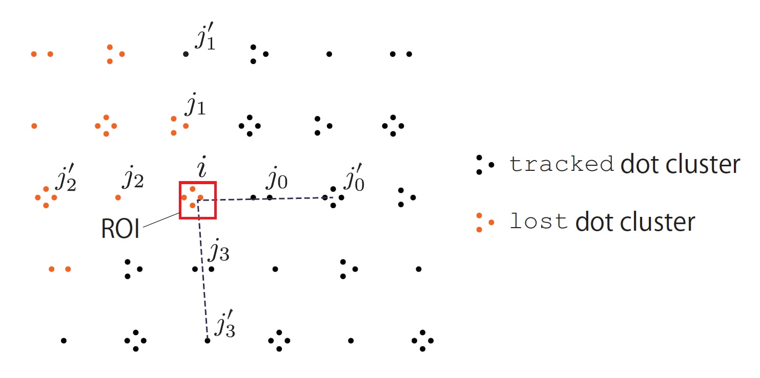
While a single frame was shown above, the system is designed to track the pattern over time. It does this by using regions of interest (ROI).
If a dot is lost for any reason, the tracking recovery system is used to estimate. It is based on an array structure of DDCM patterns. The position of a lost dot cluster is estimated by the linear extrapolation, focusing on the ROI whose center is at the extrapolated point.
There is also false positive identification in tracking. When the object is strongly deformed so self-occlusion occurs, false-positive tracking can occur mainly where the dot clusters are crowded. False-positive tracking correction needs to effectively check whether each dot cluster keeps a suitable distance between itself and the known connected dot clusters.
The whole program of detection and the frame-by-frame tracking run in parallel. In the evaluation of the pattern the computer is looking for basic types of non-rigid movement such as:
- S-deformation;
- U-deformation;
- waving deformation; and
- occlusion.
The rig is uniform so if the rig is compressed horizontally, the fabric or non-rigid surface must be bowing either away from camera or towards it. In other words, a ‘ (‘ or ‘)’ shape, ie. the surface is convex or concave. The system can do the calculation per frame for the frame-by-frame tracking in the DDCM within 1 ms.
Dynamic Warping to project
Using a PC with a NVIDIA Quadro K600, the system can warp the source imagery to match the calculated deformed shape and projects an 8-bit images at up to 1,000 fps with a minimum delay or lag of only 3 ms.
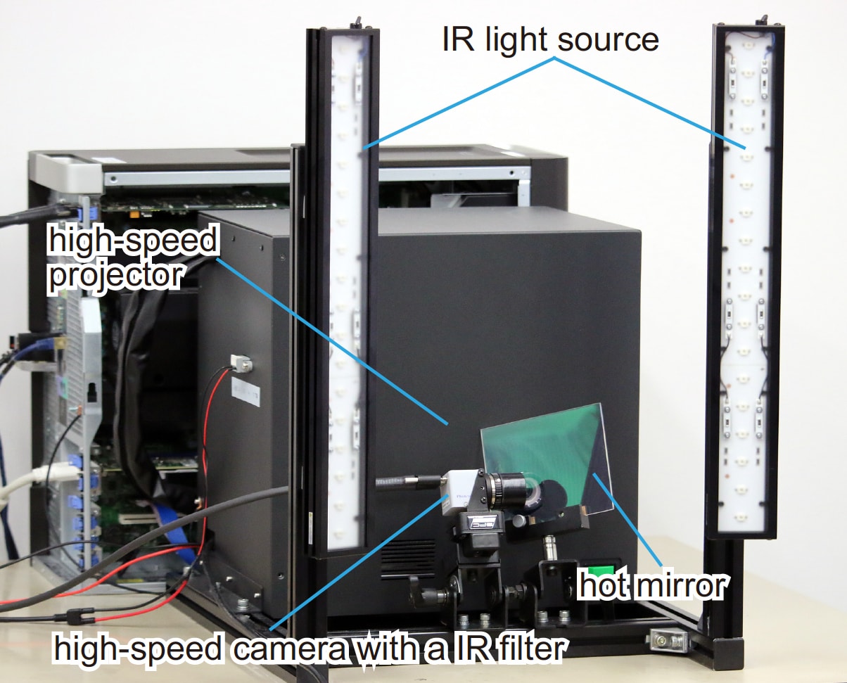
In the video, the DDCM pattern was printed on the paper and the t-shirt with the IR ink. The team used IR ink: LDP LLC IR1PenSm. This ink absorbs only near-infrared light with wavelengths from 793 nm to 820 nm and is almost invisible to the human eye. If you look at the equipment image you can see the filter for blocking visible light in front of the camera. The infrared light sources (CCS HLDL2-450X45IRDF-W,0 produce light that peaks at a wavelength of 860 nm, so that the camera observes the IR ink as black.
Below is a graph showing the speed of processing a clip, and also how the computer interpreted the frames over the 2 second clip.

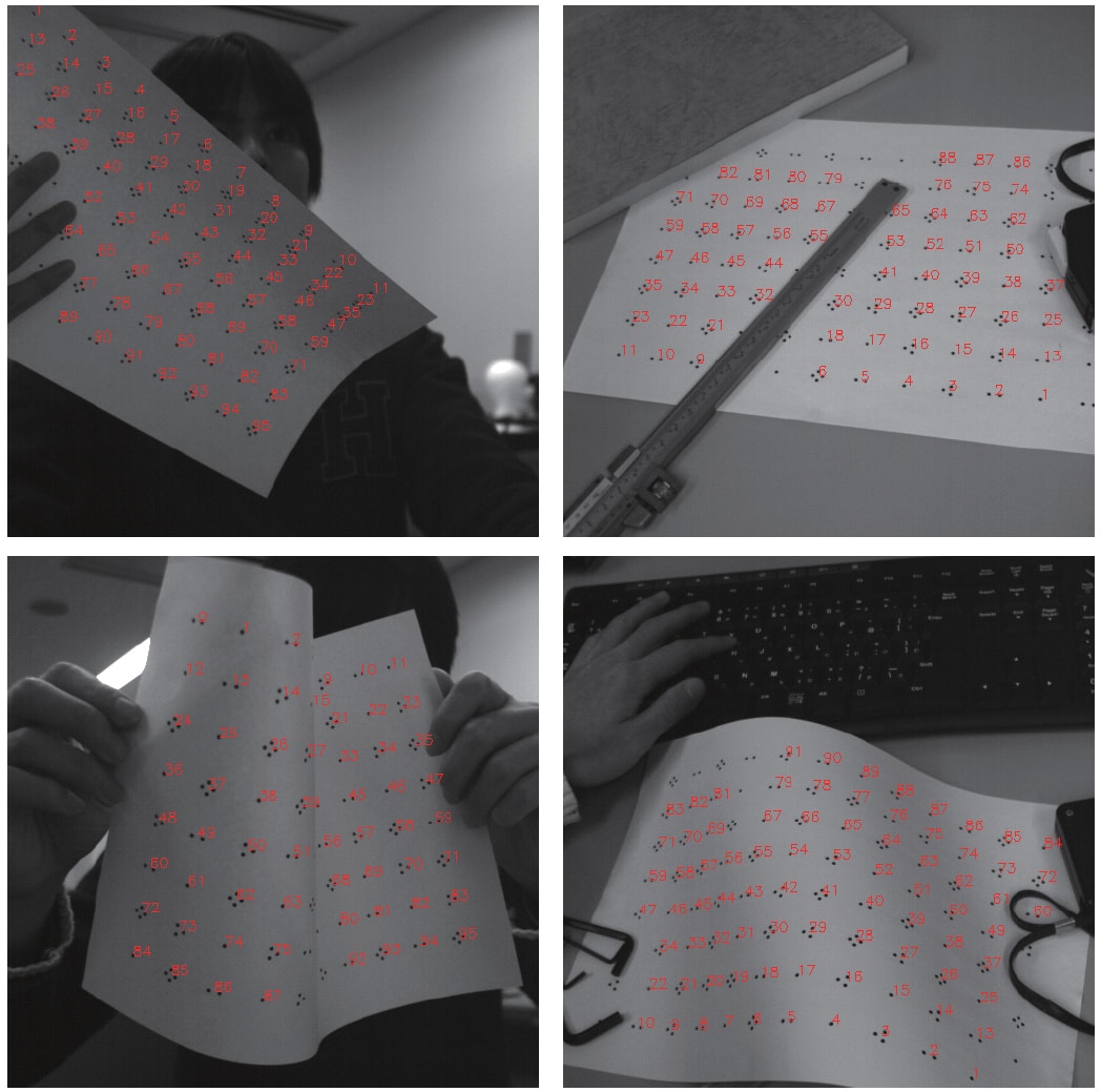
In the end the system works very effectively, even with complex folding occlusion, rapid movement and even multiple different patterns representing two different non-rigid surfaces at once.
fantastic!